-
CC2540T Extended Industrial Temperature Bluetooth® Smart Wireless MCU
- 1Device Overview
- 2Revision History
- 3Terminal Configuration and Functions
-
4Specifications
- 4.1 Absolute Maximum Ratings
- 4.2 ESD Ratings
- 4.3 Recommended Operating Conditions
- 4.4 Electrical Characteristics
- 4.5 Thermal Resistance Characteristics for RHA Package
- 4.6 General Characteristics
- 4.7 RF Receive Section
- 4.8 RF Transmit Section
- 4.9 Current Consumption With TPS62730
- 4.10 32-MHz Crystal Oscillator
- 4.11 32.768-kHz Crystal Oscillator
- 4.12 32-kHz RC Oscillator
- 4.13 16-MHz RC Oscillator
- 4.14 RSSI Characteristics
- 4.15 Frequency Synthesizer Characteristics
- 4.16 Analog Temperature Sensor
- 4.17 Comparator Characteristics
- 4.18 ADC Characteristics
- 4.19 Control Input AC Characteristics
- 4.20 SPI AC Characteristics
- 4.21 Debug Interface AC Characteristics
- 4.22 Timer Inputs AC Characteristics
- 4.23 DC Characteristics
- 4.24 Typical Characteristics
- 4.25 Typical Current Savings
- 5Detailed Description
- 6Applications, Implementation, and Layout
- 7Device and Documentation Support
- 8Mechanical Packaging and Orderable Information
- IMPORTANT NOTICE
Package Options
Mechanical Data (Package|Pins)
- RHA|40
Thermal pad, mechanical data (Package|Pins)
- RHA|40
Orderable Information
CC2540T Extended Industrial Temperature Bluetooth® Smart Wireless MCU
1 Device Overview
1.1 Features
- True Single-Chip BLE Solution: CC2540T Can Run Both Application and BLE Protocol Stack, Includes Peripherals to Interface With Wide Range of Sensors, and so forth
- Operating Temperature up to 125°C
- 6-mm × 6-mm Package
- RF
- Bluetooth® Low Energy Technology Compatible
- Excellent Link Budget (up to 97 dB), Enabling Long-Range Applications Without External Front End
- Accurate Digital Received Signal-Strength Indicator (RSSI)
- Suitable for Systems Targeting Compliance With Worldwide Radio Frequency Regulations:
- ETSI EN 300 328 and EN 300 440 Class 2 (Europe)
- FCC CFR47 Part 15 (US)
- ARIB STD-T66 (Japan)
- Layout
- Few External Components
- Reference Design Provided
- 6-mm × 6-mm VQFN40 Package
- Low Power
- Active Mode RX Down to 19.6 mA
- Active Mode TX (–6 dBm): 24 mA
- Power Mode 1 (3-μs Wake Up): 235 μA
- Power Mode 2 (Sleep Timer On): 0.9 μA
- Power Mode 3 (External Interrupts): 0.4 μA
- Wide Supply Voltage Range (2 V–3.6 V)
- Full RAM and Register Retention in All Power Modes
-
TPS62730 Compatible,
Low Power in Active Mode- RX Down to 15.8 mA (3-V Supply)
- TX (–6 dBm): 18.6 mA (3-V Supply)
- Microcontroller
- High-Performance and Low-Power 8051 Microcontroller Core
- 256KB of In-System-Programmable Flash
- 8KB of SRAM
- Peripherals
- 12-Bit ADC With Eight Channels and Configurable Resolution
- Integrated Ultralow-Power Comparator
- General-Purpose Timers (One 16-Bit, Two 8-Bit)
- 21 General-Purpose I/O (GPIO) Pins
(19 × 4 mA, 2 × 20 mA) - 32-kHz Sleep Timer With Capture
- Two Powerful USARTs With Support for Several Serial Protocols
- Full-Speed USB Interface
- IR Generation Circuitry
- Powerful Five-Channel DMA
- AES Security Coprocessor
- Battery Monitor and Temperature Sensor
- Each CC2540T Contains a Unique 48-Bit IEEE Address
-
Bluetooth v4.0 Compliant Protocol Stack for Single-Mode BLE Solution
- Complete Power-Optimized Stack, Including Controller and Host
- GAP: Central, Peripheral, Observer, or Broadcaster (Including Combination Roles)
- ATT and GATT: Client and Server
- SMP: AES-128 Encryption and Decryption
- L2CAP
- Sample Applications and Profiles
- Generic Applications for GAP Central and Peripheral Roles
- Proximity, Accelerometer, Simple Keys, and Battery GATT Services
- Multiple Configuration Options
- Single-Chip Configuration, Allowing Application to Run on CC2540T
- Network Processor Interface for Applications Running on an External Microcontroller
- BTool: Windows PC Application for Evaluation, Development, and Test
- Complete Power-Optimized Stack, Including Controller and Host
- Development Tools
- CC2540T Mini Development Kit
- SmartRF™ Software
- Supported by IAR Embedded Workbench™ Software for 8051
1.2 Applications
- 2.4-GHz Bluetooth Low Energy Systems
- Lighting
- Motor Monitoring
- Proximity Sensing
- Cable Replacement
- Power Tools
- Maintenance
- Wireless HMI and Remote Display
- USB Dongles
- Smart Phone Connectivity
1.3 Description
The CC2540T device is a cost-effective, low-power, true wireless MCU for Bluetooth low energy applications. The CC2540T enables robust BLE master or slave nodes to be built with very low total bill-of-material costs, and it can operate up to 125°C. The CC2540T combines an excellent RF transceiver with an industry-standard enhanced 8051 MCU, in-system programmable flash memory, 8KB of RAM, and many other powerful supporting features and peripherals. The CC2540T is suitable for systems where very low power consumption is required. Very low-power sleep modes are available. Short transition times between operating modes further enable low power consumption.
Combined with the Bluetooth low energy protocol stack from Texas Instruments, the CC2540TF256 forms the market’s most flexible and cost-effective single-mode Bluetooth low energy solution.
1.4 Functional Block Diagram
Figure 1-1 shows the functional block diagram of the CC2540T device.
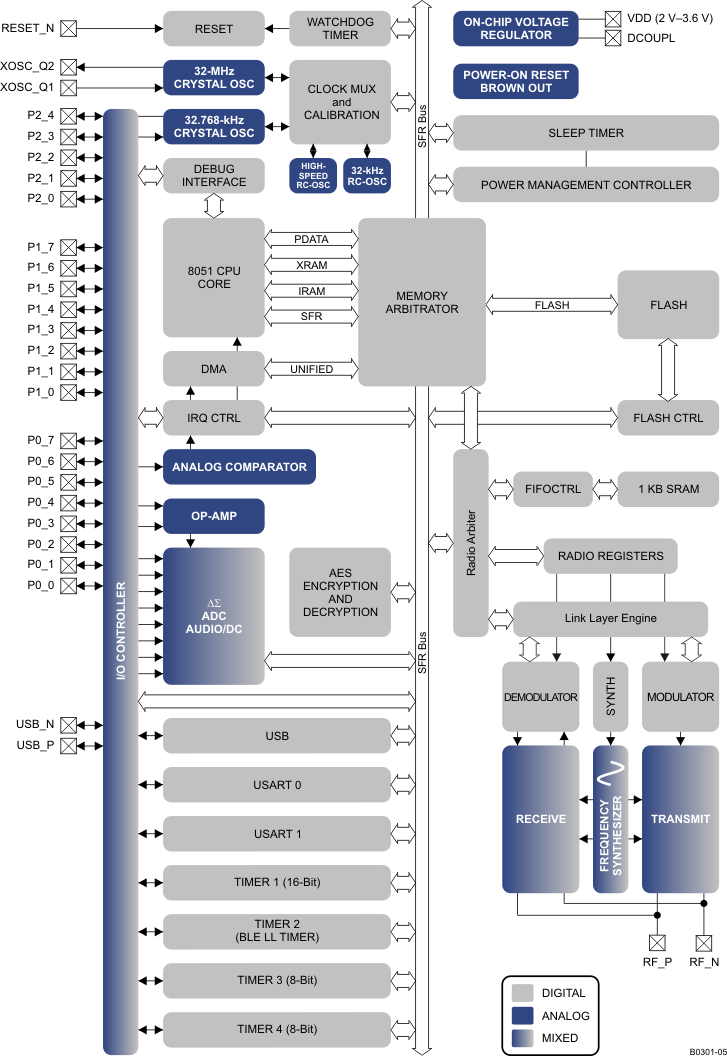 Figure 1-1 Functional Block Diagram
2 Revision History
Changes from July 2, 2015 to November 30, 2015
3 Terminal Configuration and Functions
The CC2540T pinout is shown in Figure 3-1, and a short description of the pins follows in Section 3.1.
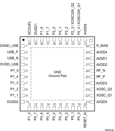
NOTE:
The exposed ground pad must be connected to a solid ground plane, as this is the ground connection for the chip.RHA Package (VQFN)
Top View
3.1 Pin Attributes
Table 3-1 Pin Attributes
| NAME | NO. | TYPE | DESCRIPTION |
|---|---|---|---|
| AVDD1 | 28 | Power (analog) | 2-V to 3.6-V analog power-supply connection |
| AVDD2 | 27 | Power (analog) | 2-V to 3.6-V analog power-supply connection |
| AVDD3 | 24 | Power (analog) | 2-V to 3.6-V analog power-supply connection |
| AVDD4 | 29 | Power (analog) | 2-V to 3.6-V analog power-supply connection |
| AVDD5 | 21 | Power (analog) | 2-V to 3.6-V analog power-supply connection |
| AVDD6 | 31 | Power (analog) | 2-V to 3.6-V analog power-supply connection |
| DCOUPL | 40 | Power (digital) | 1.8-V digital power-supply decoupling. Do not use for supplying external circuits. |
| DGND_USB | 1 | Ground pin | Connect to GND |
| DVDD_USB | 4 | Power (digital) | 2-V to 3.6-V digital power-supply connection |
| DVDD1 | 39 | Power (digital) | 2-V to 3.6-V digital power-supply connection |
| DVDD2 | 10 | Power (digital) | 2-V to 3.6-V digital power-supply connection |
| GND | — | Ground | The ground pad must be connected to a solid ground plane. |
| P0_0 | 19 | Digital I/O | Port 0.0 |
| P0_1 | 18 | Digital I/O | Port 0.1 |
| P0_2 | 17 | Digital I/O | Port 0.2 |
| P0_3 | 16 | Digital I/O | Port 0.3 |
| P0_4 | 15 | Digital I/O | Port 0.4 |
| P0_5 | 14 | Digital I/O | Port 0.5 |
| P0_6 | 13 | Digital I/O | Port 0.6 |
| P0_7 | 12 | Digital I/O | Port 0.7 |
| P1_0 | 11 | Digital I/O | Port 1.0: 20-mA drive capability |
| P1_1 | 9 | Digital I/O | Port 1.1: 20-mA drive capability |
| P1_2 | 8 | Digital I/O | Port 1.2 |
| P1_3 | 7 | Digital I/O | Port 1.3 |
| P1_4 | 6 | Digital I/O | Port 1.4 |
| P1_5 | 5 | Digital I/O | Port 1.5 |
| P1_6 | 38 | Digital I/O | Port 1.6 |
| P1_7 | 37 | Digital I/O | Port 1.7 |
| P2_0 | 36 | Digital I/O | Port 2.0 |
| P2_1 | 35 | Digital I/O | Port 2.1 |
| P2_2 | 34 | Digital I/O | Port 2.2 |
| P2_3/ XOSC32K_Q2 | 33 | Digital I/O, Analog I/O | Port 2.3/32.768 kHz XOSC |
| P2_4/ XOSC32K_Q1 | 32 | Digital I/O, Analog I/O | Port 2.4/32.768 kHz XOSC |
| RBIAS | 30 | Analog I/O | External precision bias resistor for reference current |
| RESET_N | 20 | Digital input | Reset, active-low |
| RF_N | 26 | RF I/O | Negative RF input signal to LNA during RX Negative RF output signal from PA during TX |
| RF_P | 25 | RF I/O | Positive RF input signal to LNA during RX Positive RF output signal from PA during TX |
| USB_N | 3 | Digital I/O | USB N |
| USB_P | 2 | Digital I/O | USB P |
| XOSC_Q1 | 22 | Analog I/O | 32-MHz crystal oscillator pin 1 or external-clock input |
| XOSC_Q2 | 23 | Analog I/O | 32-MHz crystal oscillator pin 2 |
4 Specifications
4.1 Absolute Maximum Ratings
over operating free-air temperature range (unless otherwise noted)(1)(2)| MIN | MAX | UNIT | ||
|---|---|---|---|---|
| Supply voltage | All supply pins must have the same voltage | –0.3 | 3.9 | V |
| Voltage on any digital pin | –0.3 | VDD + 0.3, ≤ 3.9 |
V | |
| Input RF level | 10 | dBm | ||
| Tstg | Storage temperature | –40 | 125 | °C |
4.2 ESD Ratings
| VALUE | UNIT | ||||
|---|---|---|---|---|---|
| VESD | Electrostatic discharge (ESD) performance | Human Body Model (HBM), per ANSI/ESDA/JEDEC JS001(1) | ±2000 | V | |
| Charged Device Model (CDM), per JESD22-C101(2) |
All pins | ±750 | V | ||
4.3 Recommended Operating Conditions
over operating free-air temperature range (unless otherwise noted)| MIN | MAX | UNIT | ||
|---|---|---|---|---|
| Operating ambient temperature range, TA | –40 | 125 | °C | |
| Operating supply voltage | 2 | 3.6 | V | |
4.4 Electrical Characteristics
Measured on the TI CC2540 EM reference design with TA = 25°C and VDD = 3 V.| PARAMETER | TEST CONDITIONS | MIN | TYP | MAX | UNIT | |
|---|---|---|---|---|---|---|
| Icore | Core current consumption | Power mode 1. Digital regulator on; 16-MHz RCOSC and 32-MHz crystal oscillator off; 32.768-kHz XOSC, POR, BOD and sleep timer active; RAM and register retention | 235 | µA | ||
| Power mode 2. Digital regulator off; 16-MHz RCOSC and 32-MHz crystal oscillator off; 32.768-kHz XOSC, POR, and sleep timer active; RAM and register retention | 0.9 | |||||
| Power mode 3. Digital regulator off; no clocks; POR active; RAM and register retention | 0.4 | |||||
| Low MCU activity: 32-MHz XOSC running. No radio or peripherals. No flash access, no RAM access. | 6.7 | mA | ||||
| Iperi | Peripheral current consumption(1) | Timer 1. Timer running, 32-MHz XOSC used | 90 | µA | ||
| Timer 2. Timer running, 32-MHz XOSC used | 90 | |||||
| Timer 3. Timer running, 32-MHz XOSC used | 60 | |||||
| Timer 4. Timer running, 32-MHz XOSC used | 70 | |||||
| Sleep timer, including 32.753-kHz RCOSC | 0.6 | |||||
| ADC, when converting | 1.2 | mA | ||||
4.5 Thermal Resistance Characteristics for RHA Package
| NAME | DESCRIPTION | °C/W(1)(2) | AIR FLOW (m/s)(3) |
|---|---|---|---|
| RΘJC | Junction-to-case | 16.1 | 0.00 |
| RΘJB | Junction-to-board | 5.5 | 0.00 |
| RΘJA | Junction-to-free air | 30.6 | 0.00 |
| RΘJMA | Junction-to-moving air | 0.2 | 0.00 |
| PsiJT | Junction-to-package top | 5.4 | 0.00 |
| PsiJB | Junction-to-board | 1.0 | 0.00 |
- JESD51-2, Integrated Circuits Thermal Test Method Environmental Conditions - Natural Convection (Still Air)
- JESD51-3, Low Effective Thermal Conductivity Test Board for Leaded Surface Mount Packages
- JESD51-7, High Effective Thermal Conductivity Test Board for Leaded Surface Mount Packages
- JESD51-9, Test Boards for Area Array Surface Mount Package Thermal Measurements
4.6 General Characteristics
Measured on the TI CC2540 EM reference design with TA = 25°C and VDD = 3 V.| PARAMETER | TEST CONDITIONS | MIN | TYP | MAX | UNIT |
|---|---|---|---|---|---|
| WAKE-UP AND TIMING | |||||
| Power mode 1 → Active | Digital regulator on, 16-MHz RCOSC and 32-MHz crystal oscillator off. Start-up of 16-MHz RCOSC | 4 | µs | ||
| Power mode 2 or 3 → Active | Digital regulator off, 16-MHz RCOSC and 32-MHz crystal oscillator off. Start-up of regulator and 16-MHz RCOSC | 120 | µs | ||
| Active → TX or RX | Crystal ESR = 16 Ω. Initially running on 16-MHz RCOSC, with 32-MHz XOSC OFF | 410 | µs | ||
| With 32-MHz XOSC initially on | 160 | µs | |||
| RX/TX turnaround | 150 | µs | |||
| RADIO PART | |||||
| RF frequency range | Programmable in 2-MHz steps | 2402 | 2480 | MHz | |
| Data rate and modulation format | 1 Mbps, GFSK, 250-kHz deviation | ||||
4.7 RF Receive Section
Measured on the TI CC2540 EM reference design with TA = 25°C, VDD = 3 V, fc = 2440 MHz1 Mbps, GFSK, 250-kHz deviation, Bluetooth low energy mode, and 0.1% BER(4).
| PARAMETER | TEST CONDITIONS | MIN | TYP | MAX | UNIT |
|---|---|---|---|---|---|
| Receiver sensitivity(5) | High-gain mode | –93 | dBm | ||
| Receiver sensitivity(5) | Standard mode | –87 | dBm | ||
| Saturation(1) | 6 | dBm | |||
| Co-channel rejection(1) | –5 | dB | |||
| Adjacent-channel rejection(1) | ±1 MHz | –5 | dB | ||
| Alternate-channel rejection(1) | ±2 MHz | 30 | dB | ||
| Blocking(1) | –30 | dBm | |||
| Frequency error tolerance(2) | Including both initial tolerance and drift | –250 | 250 | kHz | |
| Symbol rate error tolerance(3) | –80 | 80 | ppm | ||
| Spurious emission. Only largest spurious emission stated within each band. | Conducted measurement with a 50-Ω single-ended load. Complies with EN 300 328, EN 300 440 class 2, FCC CFR47, Part 15 and ARIB STD-T-66 | –75 | dBm | ||
| Current consumption | RX mode, standard mode, no peripherals active, low MCU activity, MCU at 250 kHz | 19.6 | mA | ||
| RX mode, high-gain mode, no peripherals active, low MCU activity, MCU at 250 kHz | 22.1 | ||||
| RX mode, high-gain mode, no peripherals active, low MCU activity, MCU at 250 kHz; TA = –40°C to 125°C, VDD = 2 V to 3.6 V, and fc = 2402 MHz to 2480 MHz |
30.5 |
4.8 RF Transmit Section
Measured on the TI CC2540 EM reference design with TA = 25°C, VDD = 3 V and fc = 2440 MHz.| PARAMETER | TEST CONDITIONS | MIN | TYP | MAX | UNIT |
|---|---|---|---|---|---|
| Output power | Delivered to a single-ended 50-Ω load through a balun using maximum recommended output power setting | 1 | 4 | dBm | |
| Delivered to a single-ended 50-Ω load through a balun using minimum recommended output power setting | –23 | ||||
| Programmable output power range | Delivered to a single-ended 50 Ω load through a balun | 27 | dB | ||
| Spurious emissions | Conducted measurement with a 50-Ω single-ended load. Complies with EN 300 328, EN 300 440 class 2, FCC CFR47, Part 15 and ARIB STD-T-66(1) | –41 | dBm | ||
| Current consumption | TX mode, –23-dBm output power, no peripherals active, low MCU activity, MCU at 250 kHz | 21.1 | mA | ||
| TX mode, –6-dBm output power, no peripherals active, low MCU activity, MCU at 250 kHz | 23.8 | ||||
| TX mode, 0-dBm output power, no peripherals active, low MCU activity, MCU at 250 kHz | 27 | ||||
| TX mode, 4-dBm output power, no peripherals active, low MCU activity, MCU at 250 kHz | 31.6 | ||||
| TX mode, 4-dBm output power, no peripherals active, low MCU activity, MCU at 250 kHz; TA = –40°C to 125°C, VDD = 2 V to 3.6 V, and fc = 2402 MHz to 2480 MHz |
39.6 | ||||
| Optimum load impedance | Differential impedance as seen from the RF port (RF_P and RF_N) toward the antenna | 70 + j30 | Ω |
4.9 Current Consumption With TPS62730
Measured on the TI CC2540TPS62730 EM reference design with TA = 25°C, VDD = 3 V, and fc = 2440 MHZ.1 Mbps, GFSK, 250-kHz deviation, Bluetooth low energy mode, 1% BER(1)
| PARAMETER | TEST CONDITIONS | MIN | TYP | MAX | UNIT | |
|---|---|---|---|---|---|---|
| Current consumption | RX mode, standard mode, no peripherals active, low MCU activity, MCU at 1 MHZ |
15.8 | mA | |||
| RX mode, high-gain mode, no peripherals active, low MCU activity, MCU at 1 MHZ |
17.8 | |||||
| TX mode, –23-dBm output power, no peripherals active, low MCU activity, MCU at 1 MHZ |
16.5 | |||||
| TX mode, –6-dBm output power, no peripherals active, low MCU activity, MCU at 1 MHZ |
18.6 | |||||
| TX mode, 0-dBm output power, no peripherals active, low MCU activity, MCU at 1 MHZ |
21 | |||||
| TX mode, 4-dBm output power, no peripherals active, low MCU activity, MCU at 1 MHZ |
24.6 | |||||
4.10 32-MHz Crystal Oscillator
Measured on the TI CC2540 EM reference design with TA = 25°C and VDD = 3 V.| PARAMETER | TEST CONDITIONS | MIN | TYP | MAX | UNIT | |
|---|---|---|---|---|---|---|
| Crystal frequency | 32 | MHz | ||||
| Crystal frequency accuracy requirement(1) | –40 | 40 | ppm | |||
| ESR | Equivalent series resistance | 6 | 60 | Ω | ||
| C0 | Crystal shunt capacitance | 1 | 7 | pF | ||
| CL | Crystal load capacitance | 10 | 16 | pF | ||
| Start-up time | 0.25 | ms | ||||
| Power-down guard time | The crystal oscillator must be in power down for a guard time before it is used again. This requirement is valid for all modes of operation. The need for power-down guard time can vary with crystal type and load. | 3 | ms | |||
4.11 32.768-kHz Crystal Oscillator
Measured on the TI CC2540 EM reference design with TA = 25°C and VDD = 3 V.| PARAMETER | TEST CONDITIONS | MIN | TYP | MAX | UNIT | |
|---|---|---|---|---|---|---|
| Crystal frequency | 32.768 | kHz | ||||
| Crystal frequency accuracy requirement(1) | –40 | 40 | ppm | |||
| ESR | Equivalent series resistance | 40 | 130 | kΩ | ||
| C0 | Crystal shunt capacitance | 0.9 | 2 | pF | ||
| CL | Crystal load capacitance | 12 | 16 | pF | ||
| Start-up time | 0.4 | s | ||||
4.12 32-kHz RC Oscillator
Measured on the TI CC2540 EM reference design with TA = 25°C and VDD = 3 V.| PARAMETER | TEST CONDITIONS | MIN | TYP | MAX | UNIT |
|---|---|---|---|---|---|
| Calibrated frequency(1) | 32.753 | kHz | |||
| Frequency accuracy after calibration | ±0.2% | ||||
| Temperature coefficient(2) | 0.4 | %/°C | |||
| Supply-voltage coefficient(3) | 3 | %/V | |||
| Calibration time(4) | 2 | ms |
4.13 16-MHz RC Oscillator
Measured on the TI CC2540 EM reference design with TA = 25°C and VDD = 3 V.| PARAMETER | TEST CONDITIONS | MIN | TYP | MAX | UNIT |
|---|---|---|---|---|---|
| Frequency(1) | 16 | MHz | |||
| Uncalibrated frequency accuracy | ±18% | ||||
| Calibrated frequency accuracy | ±0.6% | ||||
| Start-up time | 10 | µs | |||
| Initial calibration time(2) | 50 | µs |
4.14 RSSI Characteristics
Measured on the TI CC2540 EM reference design with TA = 25°C and VDD = 3 V.| PARAMETER | TEST CONDITIONS | MIN | TYP | MAX | UNIT | ||
|---|---|---|---|---|---|---|---|
| Useful RSSI range(1) | High-gain mode | –99 to –44 | dBm | ||||
| Standard mode | –90 to –35 | ||||||
| Absolute uncalibrated RSSI accuracy(1) | High-gain mode | ±4 | dB | ||||
| Step size (LSB value) | 1 | dB | |||||
4.15 Frequency Synthesizer Characteristics
Measured on the TI CC2540 EM reference design with TA = 25°C, VDD = 3 V and fc = 2440 MHz.| PARAMETER | TEST CONDITIONS | MIN | TYP | MAX | UNIT |
|---|---|---|---|---|---|
| Phase noise, unmodulated carrier | At ±1-MHz offset from carrier | –109 | dBc/Hz | ||
| At ±3-MHz offset from carrier | –112 | ||||
| At ±5-MHz offset from carrier | –119 |
4.16 Analog Temperature Sensor
Measured on the TI CC2540 EM reference design with TA = 25°C and VDD = 3 V.| PARAMETER | TEST CONDITIONS | MIN | TYP | MAX | UNIT |
|---|---|---|---|---|---|
| Output | Measured using integrated ADC, internal band-gap voltage reference, and maximum resolution | 1480 | 12-bit | ||
| Temperature coefficient | 4.5 | / 1°C | |||
| Voltage coefficient | 1 | / 0.1 V | |||
| Initial accuracy without calibration | ±10 | °C | |||
| Accuracy using 1-point calibration | ±5 | °C | |||
| Current consumption when enabled | 0.5 | mA |
4.17 Comparator Characteristics
TA = 25°C, VDD = 3 V. All measurement results are obtained using the CC2540T reference designs, post-calibration.| PARAMETER | TEST CONDITIONS | MIN | TYP | MAX | UNIT |
|---|---|---|---|---|---|
| Common-mode maximum voltage | VDD | V | |||
| Common-mode minimum voltage | –0.3 | ||||
| Input offset voltage | 1 | mV | |||
| Offset versus temperature | 16 | µV/°C | |||
| Offset versus operating voltage | 4 | mV/V | |||
| Supply current | 230 | nA | |||
| Hysteresis | 0.15 | mV |
4.18 ADC Characteristics
TA = 25°C and VDD = 3 V| PARAMETER | TEST CONDITIONS | MIN | TYP | MAX | UNIT | |
|---|---|---|---|---|---|---|
| Input voltage | VDD is voltage on AVDD5 pin | 0 | VDD | V | ||
| External reference voltage | VDD is voltage on AVDD5 pin | 0 | VDD | V | ||
| External reference voltage differential | VDD is voltage on AVDD5 pin | 0 | VDD | V | ||
| Input resistance, signal | Simulated using 4-MHz clock speed | 197 | kΩ | |||
| Full-scale signal(1) | Peak-to-peak, defines 0 dBFS | 2.97 | V | |||
| ENOB(1) | Effective number of bits | Single-ended input, 7-bit setting | 5.7 | bits | ||
| Single-ended input, 9-bit setting | 7.5 | |||||
| Single-ended input, 10-bit setting | 9.3 | |||||
| Single-ended input, 12-bit setting | 10.3 | |||||
| Differential input, 7-bit setting | 6.5 | |||||
| Differential input, 9-bit setting | 8.3 | |||||
| Differential input, 10-bit setting | 10 | |||||
| Differential input, 12-bit setting | 11.5 | |||||
| 10-bit setting, clocked by RCOSC | 9.7 | |||||
| 12-bit setting, clocked by RCOSC | 10.9 | |||||
| Useful power bandwidth | 7-bit setting, both single and differential | 0–20 | kHz | |||
| THD | Total harmonic distortion | Single ended input, 12-bit setting, –6 dBFS(1) | –75.2 | dB | ||
| Differential input, 12-bit setting, –6 dBFS(1) | –86.6 | |||||
| Signal to nonharmonic ratio | Single-ended input, 12-bit setting(1) | 70.2 | dB | |||
| Differential input, 12-bit setting(1) | 79.3 | |||||
| Single-ended input, 12-bit setting, –6 dBFS(1) | 78.8 | |||||
| Differential input, 12-bit setting, –6 dBFS(1) | 88.9 | |||||
| CMRR | Common-mode rejection ratio | Differential input, 12-bit setting, 1-kHz sine (0 dBFS), limited by ADC resolution | >84 | dB | ||
| Crosstalk | Single ended input, 12-bit setting, 1-kHz sine (0 dBFS), limited by ADC resolution | >84 | dB | |||
| Offset | Midscale | –3 | mV | |||
| Gain error | 0.68% | |||||
| DNL | Differential nonlinearity | 12-bit setting, mean(1) | 0.05 | LSB | ||
| 12-bit setting, maximum(1) | 0.9 | |||||
| INL | Integral nonlinearity | 12-bit setting, mean(1) | 4.6 | LSB | ||
| 12-bit setting, maximum(1) | 13.3 | |||||
| 12-bit setting, mean, clocked by RCOSC | 10 | |||||
| 12-bit setting, max, clocked by RCOSC | 29 | |||||
| SINAD (–THD+N) |
Signal-to-noise-and-distortion | Single ended input, 7-bit setting(1) | 35.4 | dB | ||
| Single ended input, 9-bit setting(1) | 46.8 | |||||
| Single ended input, 10-bit setting(1) | 57.5 | |||||
| Single ended input, 12-bit setting(1) | 66.6 | |||||
| Differential input, 7-bit setting(1) | 40.7 | |||||
| Differential input, 9-bit setting(1) | 51.6 | |||||
| Differential input, 10-bit setting(1) | 61.8 | |||||
| Differential input, 12-bit setting(1) | 70.8 | |||||
| Conversion time | 7-bit setting | 20 | µs | |||
| 9-bit setting | 36 | |||||
| 10-bit setting | 68 | |||||
| 12-bit setting | 132 | |||||
| Power consumption | 1.2 | mA | ||||
| Internal reference VDD coefficient | 4 | mV/V | ||||
| Internal reference temperature coefficient | 0.4 | mV/10°C | ||||
| Internal reference voltage | 1.24 | V | ||||
4.19 Control Input AC Characteristics
TA = –40°C to 125°C, VDD = 2 V to 3.6 V| PARAMETER | TEST CONDITIONS | MIN | TYP | MAX | UNIT |
|---|---|---|---|---|---|
| System clock, fSYSCLK
tSYSCLK = 1 / fSYSCLK |
The undivided system clock is 32 MHz when crystal oscillator is used. The undivided system clock is 16 MHz when calibrated 16-MHz RC oscillator is used. | 16 | 32 | MHz | |
| RESET_N low duration | See item 1 in Figure 4-1. This is the shortest pulse that is recognized as a complete reset pin request. Note that shorter pulses may be recognized but do not lead to complete reset of all modules within the chip. | 1 | µs | ||
| Interrupt pulse duration | See item 2 in Figure 4-1. This is the shortest pulse that is recognized as an interrupt request. | 20 | ns |
 Figure 4-1 Control Input AC Characteristics
4.20 SPI AC Characteristics
TA = –40°C to 125°C, VDD = 2 V to 3.6 V| PARAMETER | TEST CONDITIONS | MIN | TYP | MAX | UNIT | |
|---|---|---|---|---|---|---|
| t1 | SCK period | Master, RX and TX | 250 | ns | ||
| Slave, RX and TX | 250 | |||||
| SCK duty cycle | Master | 50% | ||||
| t2 | SSN low to SCK | Master | 63 | ns | ||
| Slave | 63 | |||||
| t3 | SCK to SSN high | Master | 63 | ns | ||
| Slave | 63 | |||||
| t4 | MOSI early out | Master, load = 10 pF | 7 | ns | ||
| t5 | MOSI late out | Master, load = 10 pF | 10 | ns | ||
| t6 | MISO setup | Master | 90 | ns | ||
| t7 | MISO hold | Master | 10 | ns | ||
| SCK duty cycle | Slave | 50% | ns | |||
| t10 | MOSI setup | Slave | 35 | ns | ||
| t11 | MOSI hold | Slave | 10 | ns | ||
| t9 | MISO late out | Slave, load = 10 pF | 95 | ns | ||
| Operating frequency | Master, TX only | 8 | MHz | |||
| Master, RX and TX | 4 | |||||
| Slave, RX only | 8 | |||||
| Slave, RX and TX | 4 | |||||
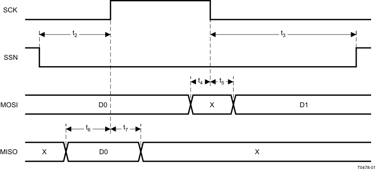 Figure 4-2 SPI Master AC Characteristics
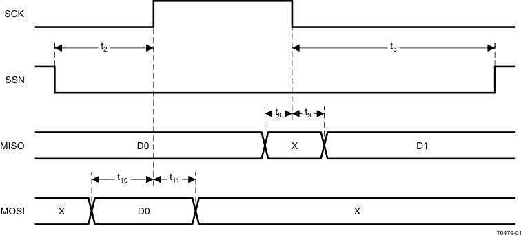 Figure 4-3 SPI Slave AC Characteristics
4.21 Debug Interface AC Characteristics
TA = –40°C to 125°C, VDD = 2 V to 3.6 V| PARAMETER | TEST CONDITIONS | MIN | TYP | MAX | UNIT | |
|---|---|---|---|---|---|---|
| fclk_dbg | Debug clock frequency (see Figure 4-4) | 12 | MHz | |||
| t1 | Allowed high pulse on clock (see Figure 4-4) | 35 | ns | |||
| t2 | Allowed low pulse on clock (see Figure 4-4) | 35 | ns | |||
| t3 | EXT_RESET_N low to first falling edge on debug clock (see Figure 4-6) | 167 | ns | |||
| t4 | Falling edge on clock to EXT_RESET_N high (see Figure 4-6) | 83 | ns | |||
| t5 | EXT_RESET_N high to first debug command (see Figure 4-6) | 83 | ns | |||
| t6 | Debug data setup (see Figure 4-5) | 2 | ns | |||
| t7 | Debug data hold (see Figure 4-5) | 4 | ns | |||
| t8 | Clock-to-data delay (see Figure 4-5) | Load = 10 pF | 30 | ns | ||
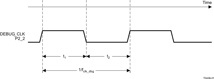 Figure 4-4 Debug Clock–Basic Timing
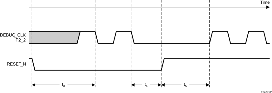 Figure 4-5 Debug Enable Timing
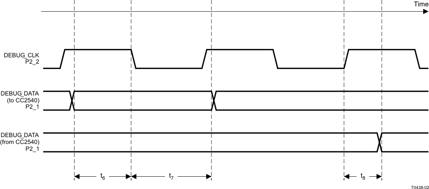 Figure 4-6 Data Setup and Hold Timing
4.22 Timer Inputs AC Characteristics
TA = –40°C to 125°C, VDD = 2 V to 3.6 V| PARAMETER | TEST CONDITIONS | MIN | TYP | MAX | UNIT |
|---|---|---|---|---|---|
| Input capture pulse duration | Synchronizers determine the shortest input pulse that can be recognized. The synchronizers operate at the current system clock rate (16 MHz or 32 MHz). | 1.5 | tSYSCLK |
4.23 DC Characteristics
TA = 25°C, VDD = 3 V| PARAMETER | TEST CONDITIONS | MIN | TYP | MAX | UNIT |
|---|---|---|---|---|---|
| Logic-0 input voltage | 0.5 | V | |||
| Logic-1 input voltage | 2.5 | V | |||
| Logic-0 input current | Input equals 0 V | –50 | 50 | nA | |
| Logic-1 input current | Input equals VDD | –50 | 50 | nA | |
| I/O-pin pullup and pulldown resistors | 20 | kΩ | |||
| Logic-0 output voltage, 4-mA pins | Output load 4 mA | 0.5 | V | ||
| Logic-1 output voltage, 4-mA pins | Output load 4 mA | 2.4 | V |
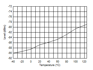
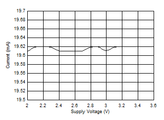
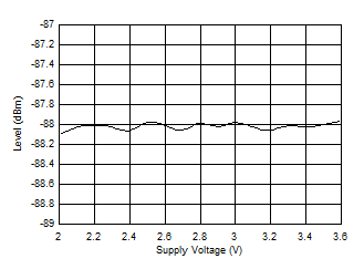
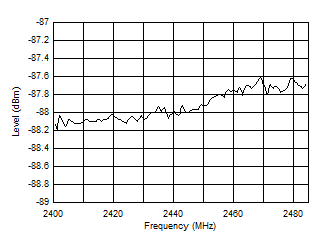
4.24 Typical Characteristics
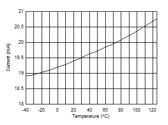
| Gain = Standard Setting | ||
| Input = –70 dBm | ||
| VCC = 3 V |
| Gain = Standard Setting | ||
| VCC = 3 V |
| Gain = Standard Setting | ||
| Input = –70 dBm | ||
| TA = 25°C |
| Gain = Standard Setting | ||
| TA = 25°C |
| Gain = Standard Setting | ||
| TA = 25°C | ||
| VCC = 3 V |
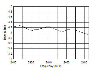
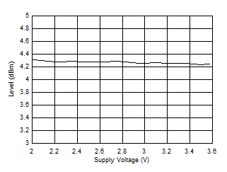
| TA = 25°C | ||
| TX Power Setting = 4 dBm | ||
| VCC = 3 V |
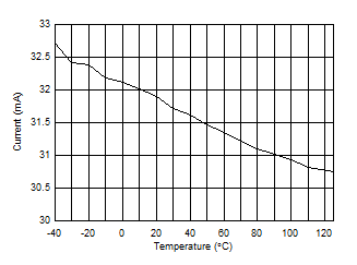
| TX Power Setting = 4 dBm | ||
| VCC = 3 V | ||
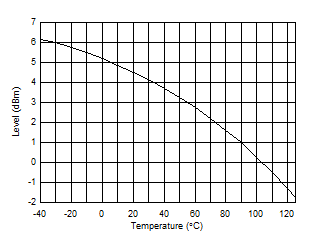
| TX Power Setting = 4 dBm | ||
| VCC = 3 V |
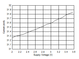
| TA = 25°C | ||
| TX Power Setting = 4 dBm | ||
| TA = 25°C | ||
| TX Power Setting = 4 dBm |
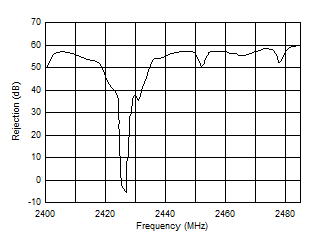
| TA = 25°C | Wanted Signal at 2426 MHz with –67 dBm Level |
||
| VCC = 3 V | |||
| Gain = Standard Setting | |||
Table 4-1 Output Power and Current Consumption(1)(2)
| TYPICAL OUTPUT POWER (dBm) |
TYPICAL CURRENT CONSUMPTION (mA) |
TYPICAL CURRENT CONSUMPTION WITH TPS62730 (mA) |
|---|---|---|
| 4 | 32 | 24.6 |
| 0 | 27 | 21 |
| –6 | 24 | 18.5 |
| –23 | 21 | 16.5 |
fc = 2440 MHz. See SWRU191 for recommended register settings.
4.25 Typical Current Savings
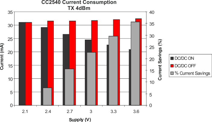 Figure 4-18 Current Savings in TX at Room Temperature
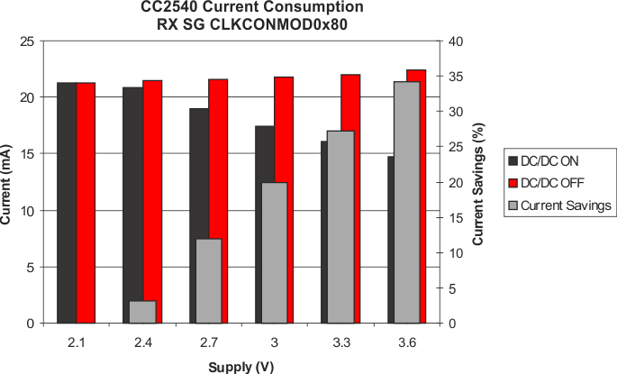 Figure 4-19 Current Savings in RX at Room Temperature
See the application note (SWRA365) for information regarding the CC2540T and TPS62730 como board and the current savings that can be achieved using the como board.