-
TLV713 Capacitor-Free, 150-mA, Low-Dropout Regulator With Foldback Current Limit for Portable Devices
- 1 Features
- 2 Applications
- 3 Description
- 4 Revision History
- 5 Pin Configurations and Functions
- 6 Specifications
- 7 Detailed Description
- 8 Application and Implementation
- 9 Power Supply Recommendations
- 10Layout
- 11Device and Documentation Support
- 12Mechanical, Packaging, and Orderable Information
- IMPORTANT NOTICE
Package Options
Mechanical Data (Package|Pins)
Thermal pad, mechanical data (Package|Pins)
- DQN|4
Orderable Information
TLV713 Capacitor-Free, 150-mA, Low-Dropout Regulator With Foldback Current Limit for Portable Devices
1 Features
- Stable Operation With or Without Capacitors
- Foldback Overcurrent Protection
- Packages:
- 1-mm × 1-mm 4-Pin X2SON
- 5-Pin SOT-23
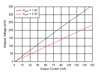
- Very Low Dropout: 230 mV at 150 mA
- Accuracy: 1%
- Low IQ: 50 µA
- Input Voltage Range: 1.4 V to 5.5 V
- Available in Fixed-Output Voltages:
1 V to 3.3 V - High PSRR: 65 dB at 1 kHz
- Active Output Discharge (P Version Only)
2 Applications
- PDAs and Battery-Powered Portable Devices
- MP3 Players and Other Hand-Held Products
- WLAN and Other PC Add-On Cards
3 Description
The TLV713 series of low-dropout (LDO) linear regulators are low quiescent current LDOs with excellent line and load transient performance and are designed for power-sensitive applications. These devices provide a typical accuracy of 1%.
The TLV713 series of devices is designed to be stable without an output capacitor. The removal of the output capacitor allows for a very small solution size. However, the TLV713 series is also stable with any output capacitor if an output capacitor is used.
The TLV713 also provides inrush current control during device power up and enabling. The TLV713 limits the input current to the defined current limit to avoid large currents from flowing from the input power source. This functionality is especially important in battery-operated devices.
The TLV713 series is available in standard DQN and DBV packages. The TLV713P provides an active pulldown circuit to quickly discharge output loads.
Device Information(1)
| DEVICE NAME | PACKAGE | BODY SIZE |
|---|---|---|
| TLV713 | X2SON (4) | 1.00 mm × 1.00 mm |
| SOT-23 (5) | 2.90 mm × 1.60 mm |
- For all available packages, see the orderable addendum at the end of the data sheet.
space
space
space
4 Revision History
Changes from E Revision (March 2015) to F Revision
- Added last sentence to Undervoltage Lockout (UVLO) sectionGo
- Added UVLO Circuit Limitation section Go
Changes from D Revision (July 2013) to E Revision
- Changed format to meet latest data sheet standards; added new sections, and moved existing sectionsGo
- Changed Features bullet about device package options Go
- Changed front-page figure Go
- Changed Pin Configuration and Functions section; updated table formatGo
- Changed Absolute Maximum Ratings table conditionsGo
- Changed Output voltage range and Junction temperature range parameter maximum specifications in Absolute Maximum Ratings table Go
- Added ESD Ratings table, Feature Description section, Device Functional Modes, Application and Implementation section, Power Supply Recommendations section, Layout section, Device and Documentation Support section, and Mechanical, Packaging, and Orderable Information sectionGo
- Corrected DBV data in Thermal Information tableGo
- Changed conditions of Electrical Characteristics table: changed VIN to VIN(nom); changed TA to TJ; corrected operating temperature range Go
- Changed TA to TJ and 85°C to 125°C throughout Electrical Characteristics table Go
- Added test conditions for line regulation parameter Go
- Changed VDO parameter in Electrical Characteristics table: all rows changed Go
- Changed Vn parameter typical specification in Electrical Characteristics table Go
- Deleted TJ parameter from Electrical Characteristics table Go
- Added TJ condiiton to ILIM parameter in Electrical Characteristics table for clarification Go
- Changed Typical Characteristics conditionsGo
- Changed Figure 1 through Figure 11 in Typical Characteristics to show improved performance definition Go
- Added new Figure 3Go
- Changed Figure 4Go
- Changed Figure 5Go
- Changed Figure 9 graph and figure titleGo
- Added new Figure 10Go
- Changed Figure 12; corrected notation on axis titles to show units per graph division (units/div)Go
- Changed Figure 13; corrected notation on axis titles to show units per graph division (units/div)Go
- Changed Figure 14; corrected notation on axis titles to show units per graph division (units/div)Go
- Changed Figure 15; corrected notation on axis titles to show units per graph division (units/div)Go
- Changed Figure 17; corrected notation on axis titles to show units per graph division (units/div)Go
- Changed Figure 19; corrected notation on axis titles to show units per graph division (units/div)Go
- Changed Figure 21; corrected notation on axis titles to show units per graph division (units/div)Go
- Changed Figure 22; corrected notation on axis titles to show units per graph division (units/div)Go
- Changed Figure 23; corrected notation on axis titles to show units per graph division (units/div)Go
- Changed Shutdown section: clarified description Go
- Changed Foldback Current Limit section: adjusted flow and clarified descriptionGo
- Changed paragraph 1 of Thermal ProtectionGo
- Changed Table 2Go
- Moved Ordering Information to Device Nomenclature section Go
Changes from C Revision (July 2013) to D Revision
- Changed document status from Mixed Status to Production DataGo
- Deleted DPW package from documentGo
- Deleted reference to DPW package from last sentence of Description sectionGo
- Deleted DPW pin out drawing from front-page graphicGo
- Deleted footnote for page 1 graphicGo
- Deleted DPW pinout drawing from Pin Configurations sectionGo
- Deleted reference to DPW package from Pin Descriptions tableGo
- Deleted DPW data from Thermal Information tableGo
- Deleted footnote 3 of Ordering Information tableGo
Changes from B Revision (December 2012) to C Revision
- Changed last Features bulletGo
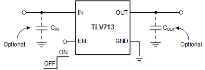
- Added Typical Application CircuitGo
- Changed last two rows of the VDO parameter in the Electrical Characteristics tableGo
Changes from A Revision (October 2012) to B Revision
- Changed footnote for page 1 graphicGo
- Added DBV data to Thermal Information tableGo
- Changed footnote 3 of Ordering Information tableGo
Changes from * Revision (September 2012) to A Revision
- Reordered Features bulletsGo
- Changed dropout range in fourth Features bulletGo
- Changed Package and Fixed-Output Voltage Features bulletsGo
- Added second and third paragraphs to Description sectionGo
- Updated DQN pin out drawingGo
- Changed DQN pinout caption in Pin Configurations sectionGo
- Changed 1.2 V to 0.9 V in description of EN pin in Pin Descriptions tableGo
- Changed DQN header row in Thermal Information tableGo
- Changed VOUT maximum specification in Electrical Characteristics tableGo
- Combined all VDO rows together in Electrical Characteristics tableGo
- Changed VDO specifications in Electrical Characteristics tableGo
- Changed ISHDN test conditions in Electrical Characteristics tableGo
- Changed Typical Characteristics conditionsGo
- Added curvesGo
- Changed junction temperature range in second paragraph of Overview sectionGo
- Updated Figure 24Go
- Deleted third paragraph from Thermal Information sectionGo
- Changed second paragraph of Input and Output Capacitor Considerations sectionGo
- Deleted curve reference from Dropout Voltage sectionGo
5 Pin Configurations and Functions

Pin Functions
| PIN | I/O | DESCRIPTION | ||
|---|---|---|---|---|
| NAME | NO. | |||
| X2SON | SOT-23 | |||
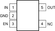
| EN | 3 | 3 | I | Enable pin. Driving EN over 0.9 V turns on the regulator.
Driving EN below 0.4 V puts the regulator into shutdown mode. |
| GND | 2 | 2 | — | Ground pin |
| IN | 4 | 1 | I | Input pin. A small capacitor is recommended from this pin to ground. See the Input and Output Capacitor Considerations section in the Feature Description for more details. |
| NC | — | 4 | — | No internal connection |
| OUT | 1 | 5 | O | Regulated output voltage pin. For best transient response, a small 1-μF ceramic capacitor is recommended from this pin to ground. See the Input and Output Capacitor Considerations section in the Feature Description for more details. |
| Thermal pad | — | — | The thermal pad is electrically connected to the GND node. Connect to the GND plane for improved thermal performance. | |


