The TPS22941/2/3/4/5 load switches provide protection to systems and loads in high-current conditions. The devices contain a 0.4-Ω current-limited P-channel MOSFET that can operate over an input voltage range of 1.62 V to 5.5 V. Current is prevented from flowing when the MOSFET is off. The switch is controlled by an on/off input (ON), which is capable of interfacing directly with low-voltage control signals. The TPS22941/2/3/4/5 includes thermal shutdown protection that prevents damage to the device when a continuous over-current condition causes excessive heating by turning off the switch.
These devices provide an integrated, robust solution to provide current limiting the output current to a safe level by switching into a constant-current mode when the ouptut load exceeds the current-limit threshold. The OC logic output asserts low during overcurrent, undervoltage, or overtemperature conditions. These additional features make the TPS22941/2/3/4/5 an ideal solution for applications where current limiting is necessary.
This family of devices are available in a SC70-5 (DCK) package. It is characterized for operation over the free-air temperature range of –40°C to 85°C.
PART NUMBER | PACKAGE | BODY SIZE (NOM) |
---|---|---|
TPS22941 | SC70 (5) | 2.00mm × 2.10 mm |
TPS22942 | ||
TPS22943 | ||
TPS22944 | ||
TPS22945 |
Changes from C Revision (November 2009) to D Revision
DEVICE | MINIMUM CURRENT LIMIT (mA) | CURRENT LIMIT BLANKING TIME (ms) |
AUTO-RESTART TIME (ms) | ON PIN ACTIVITY |
---|---|---|---|---|
TPS22941 | 40 | 10 | 80 | Active LOW |
TPS22942 | 100 | 10 | 80 | Active LOW |
TPS22943 | 40 | 0 | N/A | Active HIGH |
TPS22944 | 100 | 0 | N/A | Active HIGH |
TPS22945 | 100 | 10 | 80 | Active HIGH |
PIN | TYPE | DESCRIPTION | |
---|---|---|---|
NAME | SOT (DCK) PIN NO. |
||
VOUT | 1 | O | Switch Output. Place ceramic bypass capacitor(s) between this terminal and GND. See the Application Information section for more information. |
GND | 2 | – | Ground |
OC | 3 | O | Over current output flag: active LOW, open drain output that indicates an over current, supply under voltage, or over temperature state. |
ON | 4 | I | Switch control input. Do not leave floating. |
VIN | 5 | I | Switch Input. Place ceramic bypass capacitor(s) between this terminal and GND. See the Application Information section for more information. |
MIN | MAX | UNIT | ||||
---|---|---|---|---|---|---|
VI | Input voltage range | VIN, VOUT, ON | –0.3 | 6 | V | |
TJ | Operating junction temperature range | Internally Limited | °C |
MIN | MAX | UNIT | |||
---|---|---|---|---|---|
Tstg | Storage temperature range | –65 | 150 | °C | |
VESD | Electrostatic discharge | Human body model (HBM), per ANSI/ESDA/JEDEC JS-001, all pins(1) | –4 | 4 | kV |
Charged device model (CDM), per JEDEC specification JESD22-C101, all pins(2) | –1 | 1 |
MIN | MAX | UNIT | ||
---|---|---|---|---|
VIN | Input voltage | 1.62 | 5.5 | V |
VOUT | Output voltage | VIN | ||
TA | Ambient free-air temperature | –40 | 85 | °C |
THERMAL METRIC(1) | TPS22941/2/3/4/5 | UNIT | |
---|---|---|---|
DCK | |||
5 PINS | |||
θJA | Junction-to-ambient thermal resistance | 294 | °C/W |
θJC(top) | Junction-to-case (top) thermal resistance | 59.2 | |
θJB | Junction-to-board thermal resistance | 95.4 | |
ψJT | Junction-to-top characterization parameter | 0.7 | |
ψJB | Junction-to-board characterization parameter | 93.9 | |
θJC(bot) | Junction-to-case (bottom) thermal resistance | N/A |
PARAMETER | TEST CONDITIONS | TA | MIN | TYP(1) | MAX | UNIT | ||
---|---|---|---|---|---|---|---|---|
IIN | Quiescent current | IOUT = 0 mA, | VIN = 1.62 V to 5.5 V | Full | 40 | 80 | μA | |
IIN(OFF) | OFF-State supply current | VON = 0 V (TPS22943/4/5) or VON = VIN (TPS22941/2) |
VIN = 3.6 V, VOUT open |
Full | 1 | μA | ||
IOUT(LEAKAGE) | OFF-State switch current | VON = 0 V (TPS22943/4/5) or VON = VIN (TPS22941/2) |
VIN = 3.6 V, VOUT short to GND |
Full | 1 | μA | ||
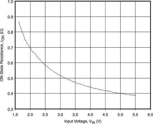
rON | ON-state resistance | IOUT = 20 mA | VIN = 5.5 V | 25°C | 0.4 | 0.5 | Ω | |
Full | 0.6 | |||||||
VIN = 3.3 V | 25°C | 0.5 | 0.6 | |||||
Full | 0.7 | |||||||
VIN = 2.5 V | 25°C | 0.6 | 0.7 | |||||
Full | 0.8 | |||||||
VIN = 1.8 V | 25°C | 0.8 | 0.9 | |||||
Full | 1.1 | |||||||
VIN = 1.62 V | 25°C | 0.9 | 1.1 | |||||
Full | 1.2 | |||||||
ION | ON input leakage current | VON = VIN or GND | Full | 1 | μA | |||
ILIM | Current limit | VIN = 3.3 V, VOUT = 3 V | TPS22941/3 | Full | 40 | 65 | 80 | mA |
TPS22942/4/5 | 100 | 150 | 200 | |||||
TSD | Thermal shutdown | Shutdown threshold | Full | 140 | °C | |||
Return from shutdown | 130 | |||||||
Hysteresis | 10 | |||||||
UVLO | Undervoltage shutdown | VIN increasing | Full | 1.32 | 1.42 | 1.52 | V | |
Undervoltage shutdown hysteresis | Full | 45 | mV | |||||
Control Output (OC) | ||||||||
Vol | OC output logic low voltage | VIN = 5 V, ISINK = 10 mA | Full | 0.1 | 0.2 | V | ||
VIN = 1.8 V, ISINK = 10 mA | 0.1 | 0.3 | ||||||
Ioz | OC output high leakage current voltage | VIN = 5 V, Switch ON | Full | 0.5 | μA | |||
Control Input (ON) | ||||||||
Vih | ON high-level input voltage | VIN = 1.8 V | Full | 1.1 | V | |||
VIN = 2.5 V | Full | 1.3 | V | |||||
VIN = 3.3 V | Full | 1.4 | V | |||||
VIN = 5.5 V | Full | 1.7 | V | |||||
Vil | ON low-level input voltage | VIN = 1.8 V | Full | 0.5 | V | |||
VIN = 2.5 V | Full | 0.7 | V | |||||
VIN = 3.3 V | Full | 0.8 | V | |||||
VIN = 5.5 V | Full | 0.9 | V | |||||
Ii | ON high-level input leakage current | VIN = 1.8 V to 5 V, Switch ON | Full | 1 | μA |
PARAMETER | TEST CONDITIONS | MIN | TYP | MAX | UNIT | ||
---|---|---|---|---|---|---|---|
tON | Turn-ON time | RL = 500 Ω, | CL = 0.1 μF | 60 | μs | ||
tOFF | Turn-OFF time | RL = 500 Ω, | CL = 0.1 μF | 30 | μs | ||
tr | VOUT rise time | RL = 500 Ω, | CL = 0.1 μF | 10 | μs | ||
tf | VOUT fall time | RL = 500 Ω, | CL = 0.1 μF | 90 | μs | ||
tBLANK | Over current blanking time | TPS22941/2/5 | 5 | 10 | 20 | ms | |
tRSTART | Auto-restart time | TPS22941/2/5 | 40 | 80 | 160 | ms | |
Short-circuit response time | VIN = VON = 3.3 V, moderate overcurrent condition | 9 | μs | ||||
VIN = VON = 3.3 V, hard short | 4 | μs |
CL = 0.1 µF | RL = 350 Ω | VIN = 3.3 V |
The TPS22941/2/3/4/5 load switches are 5.5V, current limited load switches in a SC-70 package. The devices contain a 0.4-Ω current-limited P-channel MOSFET that can operate over an input voltage range of 1.62 V to 5.5 V.
When the switch current reaches the maximum limit, the TPS22941/2/3/4/5 operates in a constant-current mode to prohibit excessive currents from causing damage. TPS22941/3 has a current limit of 40 mA and TPS22942/4/5 has a current limit of 100 mA.
For the TPS22941/2/5, if the constant current condition still persists after 10ms, these parts shut off the switch and pull the fault signal pin (OC) low. The TPS22941/2/5 have an auto-restart feature that turns the switch on again after 80 ms if the ON pin is still active. A current limit condition on the TPS22943 and on the TPS22944 immediately pull the fault signal pin low (OC pin) and the part remains in the constant-current mode until the switch current falls below the current limit.
When an overcurrent, input undervoltage, or overtemperature condition is detected, OC is set active low to signal the fault mode. OC is an open-drain MOSFET and requires a pullup resistor between VIN and OC. During shutdown, the pulldown on OC is disabled, reducing current draw from the supply.
When the switch current reaches the maximum limit, the TPS22921/2/3/4/5 operates in a constant-current mode to prohibit excessive currents from causing damage. TPS22921/3 has a current limit of 40 mA and TPS22922/4/5 has a current limit of 100 mA. A current limit condition immediately pulls the fault signal pin low (OC pin), and the part remains in the constant-current mode until the switch current falls below the current limit.
Thermal shutdown protects the part from internally or externally generated excessive temperatures. During an overtemperature condition the switch is turned off. The switch automatically turns on again if the temperature of the die drops below the threshold temperature.
When the ON pin is actively pulled high and no fault conditions are present, the switch will be turned on, connecting VIN to VOUT. When the ON pin is actively pulled low regardless of the fault condition, the switch will be turned off.
In the event that the current limit is exceeded, the device will operate in a constant-current mode and pull the OC pin low until the fault condition is removed. If the condition persists after the current limit blanking time, the device will automatically turn off.
During thermal shutdown conditions, the switch will automatically turn off and will turn back on again if the temperature of the die drops below the threshold temperature.
This section will highlight some of the design considerations when implementing this device in various applications.
The ON pin controls the state of the switch. Activating ON continuously holds the switch in the on state as long as there is no fault. An undervoltage lockout or thermal shutdown event will override the ON pin control and turn off the switch. ON is active high and has a low threshold, making it capable of interfacing with low-voltage signals.
The undervoltage lockout turns off the switch if the input voltage drops below the undervoltage lockout threshold. With the ON pin active, the input voltage rising above the undervoltage lockout threshold causes a controlled turn-on of the switch, which limits current overshoots.
If the voltage at the VOUT pin is larger than the VIN pin, large currents may flow and can cause permanent damage to the device. TPS22941/2/3/4/5 is designed to control current flow only from VIN to VOUT.
To limit the voltage drop on the input supply caused by transient in-rush currents when the switch turns on into a discharged load capacitor or a short-circuit, a capacitor needs to be placed between VIN and GND. A 1-μF ceramic capacitor, CIN, placed close to the pins is usually sufficient. Higher values of CIN can be used to further reduce the voltage drop.
A 0.1-μF capacitor, COUT, should be placed between VOUT and GND. This capacitor will prevent parasitic board inductances from forcing VOUT below GND when the switch turns off. For the TPS22941/2/3/4/5, the total output capacitance needs to be kept below a maximum value, COUT(MAX), to prevent the part from registering an over-current condition and turning-off the switch.
Due to the integrated body diode in the PMOS switch, a CIN greater than COUT is highly recommended. A COUT greater than CIN can cause VOUT to exceed VIN when the system supply is removed. This could result in current flow through the body diode from VOUT to VIN.
For this design example, use the following as the input parameters:
DESIGN PARAMETER | EXAMPLE VALUE |
---|---|
VIN | 5.0 V |
Load Current | 50mA |
To begin the design process, the designer needs to know the following:
The VIN to VOUT voltage drop in the device is determined by the RON of the device and the load current. The RON of the device depends upon the VIN condition of the device. Refer to the RON specification of the device in the Electrical Characteristics table of this datasheet.
Once the RON of the device is determined based upon the VIN conditions, use Equation 1 to calculate the VIN to VOUT voltage drop:
where
When designing this device, it is important to ensure the inrush current of the output capacitance does not cause the device to exceed the current limiting time beyond the blanking time. The maximum output capacitance can be determined from Equation 2 :
where
During normal operation as a switch, the power dissipation is small and has little effect on the operating temperature of the part. The parts with the higher current limits will dissipate the most power and that will only be,
If the part goes into current limit the maximum power dissipation will occur when the output is shorted to ground. For TPS22941/2/5, the power dissipation scales by the auto-restart time (tRESTART) and the overcurrent blanking time (tBLANK) so that the maximum power dissipated is:
When using the TPS22943 and TPS22944, a short on the output causes the part to operate in a constant current state, dissipating a worst-case power as calculated above until the thermal shutdown activates. It then cycles in and out of thermal shutdown so long as the ON pin is active and the short is present.
VDRV signal forces the device to go into over-current mode. |
CL = 0.1 µF | RL = 500 Ω | VIN = 3.3 V |
CIN = 10 µF | COUT = 1 µF |
VDRV signal forces the device to go into over-current mode. |
CL = 0.1 µF | RL = 500 Ω | VIN = 3.3 V |
CIN = 10 µF | COUT = 1 µF |
The device is designed to operate from a VIN range of 1.62-V to 5.5-V. This supply must be well regulated and placed as close to the device terminal as possible with the recommended 1µF bypass capacitor. If the supply is located more than a few inches from the device terminals, additional bulk capacitance may be required in addition to the ceramic bypass capacitors. If additional bulk capacitance is required, an electrolytic, tantalum, or ceramic capacitor of 10-µF may be sufficient.
The maximum junction temperature will be internally limited by the thermal shutdown (TSD). To calculate the maximum allowable dissipation, PD(MAX) for a given ambient temperature, use Equation 5.
where
The table below lists quick access links. Categories include technical documents, support and community resources, tools and software, and quick access to sample or buy.
PARTS | PRODUCT FOLDER | SAMPLE & BUY | TECHNICAL DOCUMENTS | TOOLS & SOFTWARE | SUPPORT & COMMUNITY |
---|---|---|---|---|---|
TPS22941 | Click here | Click here | Click here | Click here | Click here |
TPS22942 | Click here | Click here | Click here | Click here | Click here |
TPS22943 | Click here | Click here | Click here | Click here | Click here |
TPS22944 | Click here | Click here | Click here | Click here | Click here |
TPS22945 | Click here | Click here | Click here | Click here | Click here |
All other trademarks are the property of their respective owners.
These devices have limited built-in ESD protection. The leads should be shorted together or the device placed in conductive foam during storage or handling to prevent electrostatic damage to the MOS gates.
SLYZ022 — TI Glossary.
This glossary lists and explains terms, acronyms, and definitions.
The following pages include mechanical, packaging, and orderable information. This information is the most current data available for the designated devices. This data is subject to change without notice and revision of this document. For browser-based versions of this data sheet, refer to the left-hand navigation.
Texas Instruments Incorporated and its subsidiaries (TI) reserve the right to make corrections, enhancements, improvements and other changes to its semiconductor products and services per JESD46, latest issue, and to discontinue any product or service per JESD48, latest issue. Buyers should obtain the latest relevant information before placing orders and should verify that such information is current and complete. All semiconductor products (also referred to herein as "components") are sold subject to TI's terms and conditions of sale supplied at the time of order acknowledgment.
TI warrants performance of its components to the specifications applicable at the time of sale, in accordance with the warranty in TI's terms and conditions of sale of semiconductor products. Testing and other quality control techniques are used to the extent TI deems necessary to support this warranty. Except where mandated by applicable law, testing of all parameters of each component is not necessarily performed.
TI assumes no liability for applications assistance or the design of Buyers' products. Buyers are responsible for their products and applications using TI components. To minimize the risks associated with Buyers' products and applications, Buyers should provide adequate design and operating safeguards.
TI does not warrant or represent that any license, either express or implied, is granted under any patent right, copyright, mask work right, or other intellectual property right relating to any combination, machine, or process in which TI components or services are used. Information published by TI regarding third-party products or services does not constitute a license to use such products or services or a warranty or endorsement thereof. Use of such information may require a license from a third party under the patents or other intellectual property of the third party, or a license from TI under the patents or other intellectual property of TI.
Reproduction of significant portions of TI information in TI data books or data sheets is permissible only if reproduction is without alteration and is accompanied by all associated warranties, conditions, limitations, and notices. TI is not responsible or liable for such altered documentation. Information of third parties may be subject to additional restrictions.
Resale of TI components or services with statements different from or beyond the parameters stated by TI for that component or service voids all express and any implied warranties for the associated TI component or service and is an unfair and deceptive business practice. TI is not responsible or liable for any such statements.
Buyer acknowledges and agrees that it is solely responsible for compliance with all legal, regulatory and safety-related requirements concerning its products, and any use of TI components in its applications, notwithstanding any applications-related information or support that may be provided by TI. Buyer represents and agrees that it has all the necessary expertise to create and implement safeguards which anticipate dangerous consequences of failures, monitor failures and their consequences, lessen the likelihood of failures that might cause harm and take appropriate remedial actions. Buyer will fully indemnify TI and its representatives against any damages arising out of the use of any TI components in safety-critical applications.
In some cases, TI components may be promoted specifically to facilitate safety-related applications. With such components, TI's goal is to help enable customers to design and create their own end-product solutions that meet applicable functional safety standards and requirements. Nonetheless, such components are subject to these terms.
No TI components are authorized for use in FDA Class III (or similar life-critical medical equipment) unless authorized officers of the parties have executed a special agreement specifically governing such use.
Only those TI components which TI has specifically designated as military grade or "enhanced plastic" are designed and intended for use in military/aerospace applications or environments. Buyer acknowledges and agrees that any military or aerospace use of TI components which have not been so designated is solely at the Buyer's risk, and that Buyer is solely responsible for compliance with all legal and regulatory requirements in connection with such use.
TI has specifically designated certain components as meeting ISO/TS16949 requirements, mainly for automotive use. In any case of use of non-designated products, TI will not be responsible for any failure to meet ISO/TS16949.
TI E2E Community : e2e.ti.com
Mailing Address: Texas Instruments, Post Office Box 655303, Dallas, Texas 75265
Copyright© 2014, Texas Instruments Incorporated