-
TPS6106x Constant Current LED Driver With Digital and PWM Brightness Control
- 1 Features
- 2 Applications
- 3 Description
- 4 Revision History
- 5 Device Comparison Table
- 6 Pin Configuration and Functions
- 7 Specifications
- 8 Detailed Description
- 9 Application and Implementation
- 10Power Supply Recommendations
- 11Layout
- 12Device and Documentation Support
- 13Mechanical, Packaging, and Orderable Information
- IMPORTANT NOTICE
Package Options
Refer to the PDF data sheet for device specific package drawings
Mechanical Data (Package|Pins)
- YZF|8
- DRB|8
Thermal pad, mechanical data (Package|Pins)
- DRB|8
Orderable Information
TPS6106x Constant Current LED Driver With Digital and PWM Brightness Control
1 Features
- LED Driver With Integrated Overvoltage and Short-Circuit Protection
- 2.7-V to 6-V Input Voltage Range
- 500-mV or 250-mV Feedback Voltage
- TPS61060 Powers up to 3 LEDs
- TPS61061 Powers up to 4 LEDs
- TPS61062 Powers up to 5 LEDs
- PWM Brightness Control on Enable
- Digital Brightness Control on ILED
- 1-MHz Fixed Switching Frequency
- 400-mA Internal Power MOSFET Switch
- LEDs Disconnected During Shutdown
- Operates With Small-Output Capacitors
Down to 220 nF - Up to 80% Efficiency
- 8-Pin NanoFree™ Package (Chipscale, CSP)
- 3-mm × 3-mm QFN Package
2 Applications
- White LED Drivers
- Cellular Phones
- PDAs, Pocket PCs, and Smart Phones
- Digital Still Cameras
- Handheld Devices
3 Description
The TPS6106x is a high-frequency, synchronous boost converter with constant current output to drive up to five white LEDs. For maximum safety, the device features integrated overvoltage and an advanced short-circuit protection when the output is shorted to ground. The device operates with 1-MHz fixed switching frequency to allow for the use of small external components and to simplify possible EMI problems. The device comes with three different overvoltage protection thresholds (14 V, 18 V, and 23 V) to allow inexpensive and small-output capacitors with lower voltage ratings. The LED current is initially set with the external sense resistor Rs, and the feedback voltage is regulated to 500 mV or 250 mV, depending on the configuration of the ILED pin. Digital brightness control is implemented by applying a simple digital signal to the ILED pin. Alternatively, a PWM signal up to 1 kHz can be applied to the enable pin to control the brightness of the LED. During shutdown, the output is disconnected from the input to avoid leakage current through the LEDs.
Device Information(1)
| PART NUMBER | PACKAGE | BODY SIZE (NOM) |
|---|---|---|
| TPS61060, TPS61061, TPS61062 |
VSON (8) | 3.00 mm × 3.00 mm |
| DSBGA (8) | 1.446 mm × 1.446 mm |
- For all available packages, see the orderable addendum at the end of the datasheet.
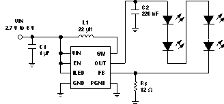
Typical Application

4 Revision History
Changes from A Revision (April 2005) to B Revision
- Added Pin Configuration and Functions section, ESD Rating table, Feature Description section, Device Functional Modes, Application and Implementation section, Power Supply Recommendations section, Layout section, Device and Documentation Support section, and Mechanical, Packaging, and Orderable Information section Go