-
UCC24650 200-V Wake-Up Monitor for Fast Transient PSR
- 1 Features
- 2 Applications
- 3 Description
- 4 Revision History
- 5 Pin Configuration and Functions
- 6 Specifications
- 7 Detailed Description
- 8 Application and Implementation
- 9 Power Supply Recommendations
- 10Layout
- 11Device and Documentation Support
- 12Mechanical, Packaging, and Orderable Information
- IMPORTANT NOTICE
Package Options
Mechanical Data (Package|Pins)
- DBV|5
Thermal pad, mechanical data (Package|Pins)
Orderable Information
UCC24650 200-V Wake-Up Monitor for Fast Transient PSR
1 Features
- Enables Excellent Load Transient Performance and Zero Standby Power
- Enables Smallest Output Capacitor for Tight ΔVOUT
- No External Components Required
- <50 µA Device Current Consumption (Typical)
- 5-V to 28-V Output Monitoring Capability
- 3% Voltage Droop Detection (Patent Pending)
- 200-V Wake-Up Switch
- Enables and Disables SR Controller, Relay Control, or Other Secondary Circuits
- SOT-23 5-Pin Package
2 Applications
- <5-mW Zero-Power Standby Applications
- Adapters and Chargers for Consumer Electronics
- Smart Phones, Tablets, Set-Top Box
- TV and Monitor Power Supplies
- Home Appliance SMPS
- Refrigerator, Washing Machine, Air Conditioners
- Industrial Power Supplies for Lighting and Home Automation
3 Description
The UCC24650 is an easy-to-use secondary-side voltage monitor that periodically measures its own VDD voltage. A relative droop of 3% from the previous reading triggers a wake-up alert signal to a receiving primary-side regulation (PSR) controller. Its low-power consumption helps achieve <5-mW Zero-Power standby loss in many applications.
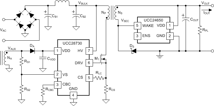
An internal 200-V MOSFET switch is applied across a ground-referenced rectifier to provide a current-limited pulse to the flyback transformer secondary winding, which couples the signal to the primary-side controller. This signal is repeated at 33 kHz until controller-driven switching activity is detected.
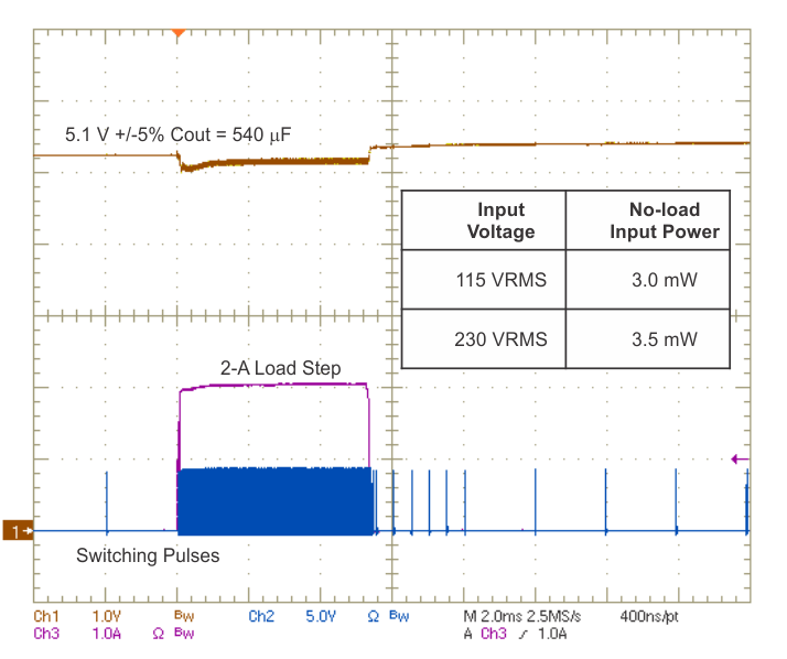
Relative-droop detection allows scaling to any voltage between 5 and 28 V. The wake-up alert function allows very-low standby frequency to minimize switching loss and reduction of output capacitance needed to respond to a heavy load step. This monitor is used with a controller capable of detecting the wake-up signal, such as the UCC28730 PSR flyback controller.
The UCC24650 also provides an enable and disable signal which can be used to control a secondary-side circuit during no-load conditions to reduce standby power loss. Such a circuit may be a synchronous rectifier controller or a relay driver, for example.
Device Information(1)
| PART NUMBER | PACKAGE | BODY SIZE (NOM) |
|---|---|---|
| UCC24650 | SOT-23 (5) | 2.92 mm × 1.30 mm |
- For all available packages, see the orderable addendum at the end of the data sheet.
Simplified Application Schematic

Rapid Full-Load Step Response

4 Revision History
| DATE | REVISION | NOTES |
|---|---|---|
| February 2015 | * | Initial release. |