SLUSB23B October 2012 – June 2015
PRODUCTION DATA.
- 1 Features
- 2 Applications
- 3 Description
- 4 Revision History
- 5 Device Comparison Table
- 6 Pin Configuration and Functions
-
7 Specifications
- 7.1 Absolute Maximum Ratings
- 7.2 ESD Ratings
- 7.3 Recommended Operating Conditions
- 7.4 Thermal Information
- 7.5 Electrical Characteristics: Power-On Reset
- 7.6 2.5-V LDO Regulator
- 7.7 Integrating ADC (Coulomb Counter) Characteristics
- 7.8 Integrated Sense Resistor Characteristics
- 7.9 ADC (Temperature and Cell Measurement) Characteristics
- 7.10 EEPROM Memory Characteristics
- 7.11 Timing Requirements: I2C-Compatible Interface Communication
- 7.12 Typical Characteristics
-
8 Detailed Description
- 8.1 Overview
- 8.2 Functional Block Diagram
- 8.3 Feature Description
- 8.4 Device Functional Modes
- 8.5
Programming
- 8.5.1
Standard Data Commands
- 8.5.1.1
Control(): 0x00 and 0x01
- 8.5.1.1.1 CONTROL_STATUS: 0x0000
- 8.5.1.1.2 DEVICE_TYPE: 0x0001
- 8.5.1.1.3 FW_VERSION: 0x0002
- 8.5.1.1.4 PREV_MACWRITE: 0x0007
- 8.5.1.1.5 CHEM_ID: 0x0008
- 8.5.1.1.6 BAT_INSERT: 0X000C
- 8.5.1.1.7 BAT_REMOVE: 0X000D
- 8.5.1.1.8 SET_HIBERNATE: 0x0011
- 8.5.1.1.9 CLEAR_HIBERNATE: 0x0012
- 8.5.1.1.10 SET_CFGUPDATE: 0x0013
- 8.5.1.1.11 SEALED: 0x0020
- 8.5.1.1.12 RESET: 0x0041
- 8.5.1.1.13 SOFT_RESET: 0x0042
- 8.5.1.2 Temperature( ): 0x02 and 0x03
- 8.5.1.3 Voltage( ): 0x04 and 0x05
- 8.5.1.4 Flags( ): 0x06 and 0x07
- 8.5.1.5 NominalAvailableCapacity( ): 0x08 and 0x09
- 8.5.1.6 FullAvailableCapacity( ): 0x0A and 0x0B
- 8.5.1.7 RemainingCapacity( ): 0x0C and 0x0D
- 8.5.1.8 FullChargeCapacity( ): 0x0E and 0x0F
- 8.5.1.9 AverageCurrent( ): 0x10 and 0x11
- 8.5.1.10 AveragePower( ): 0x18 and 0x19
- 8.5.1.11 StateOfCharge( ): 0x1C and 0x1D
- 8.5.1.12 IntTemperature( ): 0x1E and 0x1F
- 8.5.1.13 StateOfHealth( ): 0x20 and 0x21
- 8.5.1.14 OperationConfiguration( ): 0x3A and 0x3B
- 8.5.1.15 DesignCapacity( ): 0x3C and 0x3D
- 8.5.1.16 DebugX( ):
- 8.5.1.1
Control(): 0x00 and 0x01
- 8.5.2 Extended Data Commands
- 8.5.3 Block Data Interface
- 8.5.4 Access Modes
- 8.5.5 Data Block Summary
- 8.5.6 Detecting Charge Termination
- 8.5.7 Communications
- 8.5.1
Standard Data Commands
- 8.6 Register Maps
- 9 Application and Implementation
- 10Power Supply Recommendations
- 11Layout
- 12Device and Documentation Support
- 13Mechanical, Packaging, and Orderable Information
Package Options
Mechanical Data (Package|Pins)
- YZF|15
Thermal pad, mechanical data (Package|Pins)
Orderable Information
1 Features
- Single-Series Cell Li-Ion Battery Fuel Gauge
- Resides on System Board
- Supports Embedded or Removable Batteries
- Powered Directly From Battery With Integrated LDO
- Low-Value Integrated Sense Resistor
(10 mΩ, Typical)
- Easy-to-Configure Fuel Gauging Based on Patented Impedance Track™ Technology
- Reports Remaining Capacity and State of Charge (SOC) With Smoothing Filter
- Automatically Adjusts for Battery Aging, Self-Discharge, Temperature, and Rate Changes
- Battery State-of-Health (Aging) Estimation
- Microcontroller Peripheral Supports:
- 400-kHz I2C Serial Interface
- Configurable SOC Interrupt or
Battery Low Digital Output Warning - Internal Temperature Sensor or
Host-Reported Temperature
2 Applications
- Smart Phones, Feature Phones, and Tablets
- Digital Still and Video Cameras
- Handheld Terminals
- MP3 or Multimedia Players
3 Description
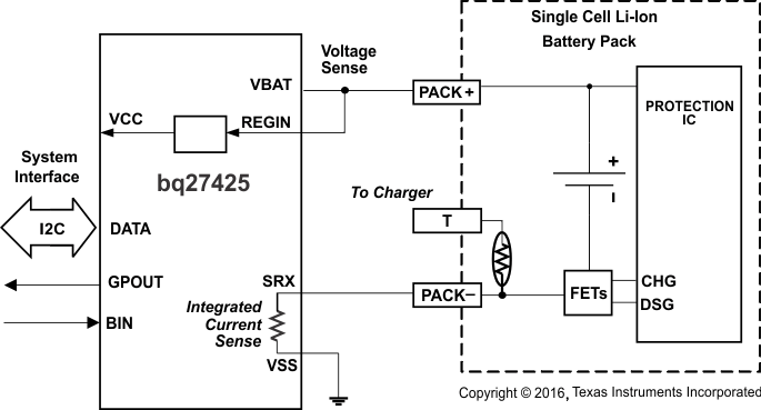
The Texas Instruments bq27425-G2 fuel gauge is an easy-to-configure microcontroller peripheral that provides system-side fuel gauging for single-cell Li-Ion batteries. The device requires minimal user configuration and system microcontroller firmware development.
The fuel gauge uses the patented Impedance Track™ algorithm for fuel gauging, and provides information such as remaining battery capacity (mAh), state-of-charge (%), and battery voltage (mV).
Battery fuel gauging with the bq27425-G2 fuel gauge requires connections only to PACK+ (P+) and PACK– (P–) for a removable battery pack or embedded battery circuit. The 15-pin, 2.69 mm × 1.75 mm, 0.5-mm pitch chip scale package (DSBGA) is ideal for space-constrained applications.
Device Information(1)
| DEVICE NAME | PACKAGE | BODY SIZE (NOM) |
|---|---|---|
| bq27425-G2 | DSBGA (15) | 2.69 mm × 1.75 mm |
