ZHCSDU1A May 2014 – June 2015 ADC32J42 , ADC32J43 , ADC32J44 , ADC32J45
PRODUCTION DATA.
- 1 特性
- 2 应用
- 3 说明
- 4 修订历史记录
- 5 Device Comparison Table
- 6 Pin Configuration and Functions
-
7 Specifications
- 7.1 Absolute Maximum Ratings
- 7.2 ESD Ratings
- 7.3 Recommended Operating Conditions
- 7.4 Thermal Information
- 7.5 Electrical Characteristics
- 7.6 Electrical Characteristics: ADC32J44, ADC32J45
- 7.7 Electrical Characteristics: ADC32J42, ADC32J43
- 7.8 AC Performance: ADC32J45
- 7.9 AC Performance: ADC32J44
- 7.10 AC Performance: ADC32J43
- 7.11 AC Performance: ADC32J42
- 7.12 Digital Characteristics
- 7.13 Timing Requirements
- 7.14 Typical Characteristics: ADC32J45
- 7.15 Typical Characteristics: ADC32J44
- 7.16 Typical Characteristics: ADC32J43
- 7.17 Typical Characteristics: ADC32J42
- 7.18 Typical Characteristics: Common Plots
- 7.19 Typical Characteristics: Contour Plots
- 8 Parameter Measurement Information
-
9 Detailed Description
- 9.1 Overview
- 9.2 Functional Block Diagram
- 9.3 Feature Description
- 9.4 Device Functional Modes
- 9.5 Programming
- 9.6
Register Maps
- 9.6.1 Summary of Special Mode Registers
- 9.6.2
Serial Register Descriptions
- 9.6.2.1 Register 01h (address = 01h)
- 9.6.2.2 Register 03h (address = 03h)
- 9.6.2.3 Register 04h (address = 04h)
- 9.6.2.4 Register 06h (address = 06h)
- 9.6.2.5 Register 07h (address = 07h)
- 9.6.2.6 Register 08h (address = 08h)
- 9.6.2.7 Register 09h (address = 09h)
- 9.6.2.8 Register 0Ah (address = 0Ah)
- 9.6.2.9 Register 0Bh (address = 0Bh)
- 9.6.2.10 Register 0Ch (address = 0Ch)
- 9.6.2.11 Register 0Dh (address = 0Dh)
- 9.6.2.12 Register 0Eh (address = 0Eh)
- 9.6.2.13 Register 0Fh (address = 0Fh)
- 9.6.2.14 Register 13h (address = 13h)
- 9.6.2.15 Register 15h (address = 15h)
- 9.6.2.16 Register 27h (address = 27h)
- 9.6.2.17 Register 2Ah (address = 2Ah)
- 9.6.2.18 Register 2Bh (address = 2Bh)
- 9.6.2.19 Register 2Fh (address = 2Fh)
- 9.6.2.20 Register 30h (address = 30h)
- 9.6.2.21 Register 31h (address = 31h)
- 9.6.2.22 Register 34h (address = 34h)
- 9.6.2.23 Register 3Ah (address = 3Ah)
- 9.6.2.24 Register 3Bh (address = 3Bh)
- 9.6.2.25 Register 3Ch (address = 3Ch)
- 9.6.2.26 Register 422h (address = 422h)
- 9.6.2.27 Register 434h (address = 434h)
- 9.6.2.28 Register 522h (address = 522h)
- 9.6.2.29 Register 534h (address = 534h)
- 10Application and Implementation
- 11Power-Supply Recommendations
- 12Layout
- 13器件和文档支持
- 14机械、封装和可订购信息
1 特性
- 双通道
- 14 位分辨率
- 单电源:1.8V
- 支持 1 分频、2 分频和 4 分频的灵活输入时钟缓冲器
-
fIN = 70MHz 时,信噪比 (SNR) = 72.2dBFS,无杂散动态范围 (SFDR) = 87dBc - 超低功耗:
- 160MSPS 时为每通道 227mW
- 通道隔离:105dB
- 内部抖动
- JESD204B 串口:
- 兼容子类 0、1、2,速率最高达 3.2Gbps
- 支持每个 ADC 一条通道(高达 160MSPS)
- 支持多芯片同步
- 与 12 位版本器件 (ADC32J2X) 引脚到引脚兼容
- 封装:超薄四方扁平无引线 (VQFN)-48 (7mm x 7mm)
2 应用
- 多载波、多模式蜂窝基站
- 雷达和智能天线阵列
- 炮弹制导
- 电机控制反馈
- 网络和矢量分析器
- 通信测试设备
- 无损检测
- 微波接收器
- 软件定义无线电 (SDR)
- 正交和分集无线电接收器
3 说明
ADC32J4x 属于高线性度、超低功耗、双通道、14 位、50MSPS 至 160MSPS 模数转换器 (ADC) 系列。 此类器件专门设计用于支持具有宽动态范围需求且要求苛刻的高输入频率信号。 时钟输入分频器可给予系统时钟架构设计更高的灵活性,SYSREF 输入可实现整个系统同步。 ADC32J4x 系列支持 JESD204B 接口,减少了接口线路数,从而实现高系统集成度。 JESD204B 接口是串行接口,仅通过一个差分对即可串行输出每个 ADC 的数据。 内部锁相环 (PLL) 会将传入的 ADC 采样时钟乘以 20,以获得串行化各通道的 14 位数据时所使用的位时钟。 该器件支持子类 1,接口速率高达 3.2Gbps。
器件信息(1)
| 器件型号 | 封装 | 封装尺寸(标称值) |
|---|---|---|
| ADC32J4x | VQFN (48) | 7.00mm x 7.00mm |
- 要了解所有可用封装,请见数据表末尾的封装选项附录。
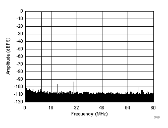
fS = 160MSPS 且 fIN = 10MHz 时的性能
(SNR = 72.5dBFS,SFDR = 92dBc)
