ZHCS455F December 2010 – July 2015 ISO7420E , ISO7420FE , ISO7421E , ISO7421FE
PRODUCTION DATA.
- 1 特性
- 2 应用
- 3 说明
- 4 修订历史记录
- 5 Pin Configuration and Functions
-
6 Specifications
- 6.1 Absolute Maximum Ratings
- 6.2 ESD Ratings
- 6.3 Recommended Operating Conditions
- 6.4 Thermal Information
- 6.5 Electrical Characteristics: VCC1 and VCC2 = 5 V ± 10%
- 6.6 Electrical Characteristics: VCC1 = 5 V ± 10%, VCC2 = 3.3 V ± 10%
- 6.7 Electrical Characteristics: VCC1 = 3.3 V ± 10%, VCC2 = 5 V ± 10%
- 6.8 Electrical Characteristics: VCC1 and VCC2 = 3.3 V ± 10%
- 6.9 Power Dissipation Characteristics
- 6.10 Switching Characteristics: VCC1 and VCC2 = 5 V ± 10%
- 6.11 Switching Characteristics: VCC1 = 5 V ± 10%, VCC2 = 3.3 V ± 10%
- 6.12 Switching Characteristics: VCC1 = 3.3 V ± 10%, VCC2 = 5 V ± 10%
- 6.13 Switching Characteristics: VCC1 and VCC2 = 3.3 V ± 10%
- 6.14 Typical Characteristics
- 7 Parameter Measurement Information
- 8 Detailed Description
- 9 Applications and Implementation
- 10Power Supply Recommendations
- 11Layout
- 12器件和文档支持
- 13机械、封装和可订购信息
1 特性
2 应用
- 在下列使用中的光电耦合器替代产品:
- 工业用 FieldBus
- ProfiBus
- ModBus
- DeviceNet™数据总线
- 伺服控制接口
- 电机控制
- 电源
- 电池组
- 工业用 FieldBus
3 说明
ISO742x 可提供符合 UL 标准的长达 1 分钟且高达 2500VRMS 的电流隔离,以及符合 VDE 标准的 4242VPK 隔离。这些器件有 2 个隔离通道。每个通道有一个逻辑输入和输出缓冲器,这两个器件由一个硅二极管(SiO2) 绝缘隔栅进行分离。通过与隔离电源一起使用,这些器件可防止数据总线或者其它电路上的噪音电流进入本地接地并干扰或者损坏敏感电路。ISO7420 的两个通道方向相同,而 ISO7421 的两个通道方向相反。如果出现输入功率或信号损失,则后缀为“F”的器件默认输出“低”电平,后缀没有“F”的器件则默认输出“高”电平。ISO742x 未集成噪声滤波器,因而传播延迟相对短暂。
这些器件具有晶体管晶体管逻辑电路 (TTL) 输入阈值,工作电压范围为 3V 到 5.5V。当由一个 3.3V 电源供电时,所有输入均为 5V 耐压。
器件信息(1)
| 器件型号 | 封装 | 封装尺寸(标称值) |
|---|---|---|
| ISO7420E | SOIC (8) | 4.90mm x 3.91mm |
| ISO7420FE | ||
| ISO7421E | ||
| ISO7421FE |
- 要了解所有可用封装,请见数据表末尾的可订购产品附录。
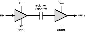
简化电路原理图

4 修订历史记录
Changes from E Revision (January 2013) to F Revision
- 已根据最新的 TI 标准更改数据表格式Go
- Added 引脚配置和功能部分,ESD 额定值表,特性 描述 部分,器件功能模式,应用和实施部分,电源相关建议部分,布局部分,器件和文档支持部分以及机械、封装和可订购信息部分Go
- 已删除 说明部分的如下文本:“CC 级器件集成有应用于恶劣环境的 10ns 滤波器,在这种环境下,器件的输入引脚上可能存在短噪声脉冲。”Go
- VDE 标准更改为 DIN V VDE V 0884-10 (VDE V 0884-10):2006-12 Go
- Deleted CC-grade from tPLH, tPHL in the Switching Characteristics tableGo
- Deleted CC-grade from tPLH, tPHL in the Switching Characteristics tableGo
- Deleted CC-grade from tPLH, tPHL in the Switching Characteristics tableGo
- Deleted CC-grade from tPLH, tPHL in the Switching Characteristics tableGo
- Changed the Available Options Table To the Feature Description tableGo
Changes from D Revision (December 2011) to E Revision
- 已删除器件 ISO7420FCC 和 ISO7421FCCGo
- Changed the NOTE: textGo
- Added table Note to VIORMGo
- Changed Z to Undetermined for the OUTPUT OUTA, OUTB column of the FUNCTION TABLEGo
Changes from C Revision (March 2011) to D Revision
Changes from B Revision (January 2011) to C Revision
- 已添加器件 ISO7420FCC 和 ISO7421FCCGo
- 已将特性要点更改为:低传播延迟:7ns,典型值(E 级)Go
- 已将特性要点更改为:低脉冲偏移:200ps,典型值(E 级)Go
- 已更改安全及管理批准列表Go
- 已更改数据表 说明Go
- Changed the Supply Current values for ISO7421x at 10, 25, and 50 MbpsGo
- Changed the Supply Current values for ISO7421x at 10, 25, and 50 MbpsGo
- Changed the Supply Current values for ISO7421x at 10, 25, and 50 MbpsGo
- Changed the Supply Current values for ISO7421x 25 and 50 MbpsGo
- Added CC-grade and valued to tPLH, tPHL in the Switching Characteristics tableGo
- Added ISO7421x values for Pulse width distortion, Channel-to-channel output skew time, and Part-to-part skew timeGo
- Added CC-grade and valued to tPLH, tPHL in the Switching Characteristics tableGo
- Added ISO7421x values for Pulse width distortion and Channel-to-channel output skew timeGo
- Added CC-grade and valued to tPLH, tPHL in the Switching Characteristics tableGo
- Added CC-grade and valued to tPLH, tPHL in the Switching Characteristics tableGo
- Added graphs Figure 5, Figure 6, Figure 7, and Figure 8Go
- Added graphs Figure 14 and Figure 15Go
- Changed Note 1 Figure 16Go
- Changed Figure 17Go
- Changed the Available Options TableGo
- Changed Isolation resistance test conditionsGo
- Changed the values of VIORM and VPR in the INSULATION CHARACTERISTICS tableGo
- Changed the value of VIOTM in the INSULATION CHARACTERISTICS table From: 4000 To: 4242Go
- Changed Figure 21Go
- Changed PU to X in the last row of the FUNCTION TABLEGo
- Added section: SUPPLY CURRENT EQUATIONSGo
Changes from A Revision (December 2010) to B Revision
- 将特性着重号从:ISO7421:1Mbps下为TBDmA,25Mbps下为TBDmA改到:ISO7421:1Mbps下为1.8mA,25Mbps下为2.8mAGo
- Updated the ISO7421x Supply Current values for VCC1 and VCC2 = 5VGo
- Updated the ISO7421x Supply Current values for VCC1 = 5V and VCC2 = 3.3VGo
- Updated the ISO7421x Supply Current values for VCC1 = 3.3V and VCC2 = 5VGo
- Updated the ISO7421x Supply Current values for VCC1 and VCC2 = 3.3VGo
Changes from * Revision (December 2010) to A Revision
- Changed the Max values for Supply current for VCC1 and VCC2, CL = 15pFGo