SBOS231I January 2002 – November 2015 TMP100 , TMP101
PRODUCTION DATA.
- 1 Features
- 2 Applications
- 3 Description
- 4 Revision History
- 5 Pin Configuration and Functions
- 6 Specifications
-
7 Detailed Description
- 7.1 Overview
- 7.2 Functional Block Diagram
- 7.3 Feature Description
- 7.4 Device Functional Modes
- 7.5 Programming
- 8 Application and Implementation
- 9 Power Supply Recommendations
- 10Layout
- 11Device and Documentation Support
- 12Mechanical, Packaging, and Orderable Information
1 Features
- Digital Output: SMBus™, Two-Wire, and I2C Interface Compatibility
- Resolution: 9 to 12 Bits, User-Selectable
- Accuracy:
- ±1°C (Typical) from –55°C to 125°C
- ±2°C (Maximum) from –55°C to 125°C
- Low Quiescent Current: 45-μA, 0.1-μA Standby
- Wide Supply Range: 2.7 V to 5.5 V
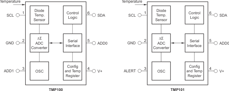
- TMP100 Features Two Address Pins
- TMP101 Features One Address Pin and an ALERT Pin
- 6-Pin SOT-23 Package
2 Applications
- Power-Supply Temperature Monitoring
- Computer Peripheral Thermal Protection
- Notebook Computers
- Cell Phones
- Battery Management
- Office Machines
- Thermostat Controls
- Environmental Monitoring and HVAC
- Electromechanical Device Temperature
3 Description
The TMP100 and TMP101 devices are digital temperature sensors ideal for negative temperature coefficient (NTC) and positive temperature coefficient (PTC) thermistor replacement. The devices offer a typical accuracy of ±1°C without requiring calibration or external component signal conditioning. Device temperature sensors are highly linear and do not require complex calculations or look-up tables to derive the temperature. The on-chip, 12-bit ADC offers resolutions down to 0.0625°C. The devices are available in 6-Pin SOT-23 packages.
The TMP100 and TMP101 devices feature SMBus, Two-Wire, and I2C interface compatibility. The TMP100 device allows up to eight devices on one bus. The TMP101 device offers an SMBus Alert function with up to three devices per bus.
The TMP100 and TMP101 devices are ideal for extended temperature measurement in a variety of communication, computer, consumer, environmental, industrial, and instrumentation applications.
The TMP100 and TMP101 devices are specified for operation over a temperature range of −55°C to 125°C.
Device Information(1)
| PART NUMBER | PACKAGE | BODY SIZE (NOM) |
|---|---|---|
| TMP100 | SOT-23 (6) | 2.90 mm × 1.60 mm |
| TMP101 | SOT-23 (6) | 2.90 mm × 1.60 mm |
- For all available packages, see the orderable addendum at the end of the data sheet.
Simplified Schematics
