ZHCSE38A August   2015  – August 2015

PRODUCTION DATA.  

  1. 特性
  2. 应用
  3. 说明
  4. 修订历史记录
  5. Device Comparison Table
  6. Pin Configuration and Functions
  7. Specifications
    1. 7.1 Absolute Maximum Ratings
    2. 7.2 ESD Ratings
    3. 7.3 Recommended Operating Conditions
    4. 7.4 Thermal Information
    5. 7.5 Electrical Characteristics
    6. 7.6 Timing Requirements
    7. 7.7 Typical Characteristics
  8. Detailed Description
    1. 8.1 Overview
    2. 8.2 Functional Block Diagram
    3. 8.3 Feature Description
      1. 8.3.1 GND
      2. 8.3.2 VIN
      3. 8.3.3 dV/dT
      4. 8.3.4 BFET
      5. 8.3.5 EN/UVLO
      6. 8.3.6 ILIM
    4. 8.4 Device Functional Modes
  9. Application and Implementation
    1. 9.1 Application Information
    2. 9.2 Typical Applications
      1. 9.2.1 Simple 3.7-A eFuse Protection for Set Top Boxes
        1. 9.2.1.1 Design Requirements
        2. 9.2.1.2 Detailed Design Procedure
          1. 9.2.1.2.1 Step by Step Design Procedure
          2. 9.2.1.2.2 Programming the Current-Limit Threshold: RILIM Selection
          3. 9.2.1.2.3 Undervoltage Lockout Set Point
          4. 9.2.1.2.4 Setting Output Voltage Ramp Time (TdVdT)
            1. 9.2.1.2.4.1 Case 1: Start-Up without Load: Only Output Capacitance COUT Draws Current During Start-Up
            2. 9.2.1.2.4.2 Case 2: Start-Up with Load: Output Capacitance COUT and Load Draws Current During Start-Up
          5. 9.2.1.2.5 Support Component Selection - CVIN
        3. 9.2.1.3 Application Curves
      2. 9.2.2 Inrush and Reverse Current Protection for Hold-Up Capacitor Application (for example, SSD)
        1. 9.2.2.1 Design Requirements
        2. 9.2.2.2 Detailed Design Procedure
          1. 9.2.2.2.1 Programming the Current-Limit Threshold: RILIM Selection
          2. 9.2.2.2.2 Undervoltage Lockout Set Point
          3. 9.2.2.2.3 Setting Output Voltage Ramp Time (TdVdT)
        3. 9.2.2.3 Application Curves
  10. 10Power Supply Recommendations
    1. 10.1 Transient Protection
    2. 10.2 Output Short-Circuit Measurements
  11. 11Layout
    1. 11.1 Layout Guidelines
    2. 11.2 Layout Example
  12. 12器件和文档支持
    1. 12.1 器件支持
      1. 12.1.1 Third-Party Products Disclaimer
    2. 12.2 文档支持
      1. 12.2.1 相关文档
    3. 12.3 相关链接
    4. 12.4 社区资源
    5. 12.5 商标
    6. 12.6 静电放电警告
    7. 12.7 Glossary
  13. 13机械、封装和可订购信息

封装选项

机械数据 (封装 | 引脚)
散热焊盘机械数据 (封装 | 引脚)
订购信息

1 特性

  • VOPERATING = 4.5V 至 13.8V,VABSMAX = 20V
  • 集成 28mΩ 导通金属氧化物半导体场效应晶体管 (MOSFET)
  • 15V 固定过压钳位
  • 1A 至 5A 可调电流 ILIMIT
  • ±8% ILIMIT 精度(3.7A 时)
  • 支持反向电流阻断
  • 可编程 OUT(输出)转换率,欠压闭锁 (UVLO)
  • 内置热关断
  • UL2367 认证正在处理中
  • 单点故障测试期间安全 (UL60950)
  • 小型封装尺寸 - 10L (3mm x 3mm) 超薄小外形尺寸无引线封装 (VSON)

2 应用

  • 适配器供电器件
  • 硬盘 (HDD) 和固态硬盘 (SSD)
  • 机顶盒
  • 服务器/辅助 (AUX) 电源
  • 风扇控制
  • PCI/PCIe 卡

3 说明

TPS25924x 系列电子熔丝是采用小型封装的高度集成电路保护和电源管理解决方案。 该器件使用极少的外部组件并可提供多重保护模式。 它们能够有效地防止过载、短路、电压浪涌、过高浪涌电流和反向电流。

电流限制级别可通过一个外部电阻设定。 内部钳位电路可将过电压限制在一个安全的固定最大值,无需使用外部组件。

具有特殊电压斜坡要求的应用可以使用单个电容来设定 dV/dT,以确保达到适当的输出斜坡速率。 许多系统(例如 SSD)禁止将储存的电容能量通过 FET 二极管倒流到降压或短路输入总线。 BFET 引脚专用于这类系统。 外部 NFET 可与 TPS25924x 输出形成“背靠背 (B2B)”连接,而由 BFET 驱动的栅极可防止电流从负载流回电源(请参见Figure 43)。

器件信息(1)

器件型号 封装 封装尺寸(标称值)
TPS259241 VSON (10) 3.00mm × 3.00mm
TPS259240
  1. 要了解所有可用封装,请见数据表末尾的可订购产品附录。

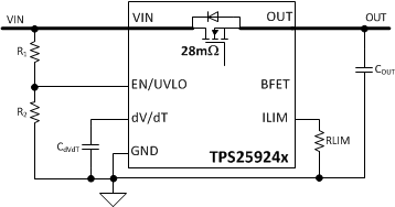
应用电路原理图

TPS259240 TPS259241 top_page_slvscu9.gif

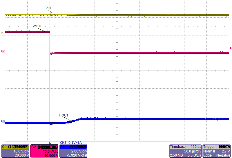
瞬态:输出短路

TPS259240 TPS259241 FP_24_35_slvscu9.png