SBOA179A December 2016 – September 2021 AMC1304L05 , AMC1304L25 , AMC1304M05 , AMC1304M25 , AMC1305L25 , AMC1305M05 , AMC1305M25 , INA209 , INA210 , INA210-Q1 , INA219 , INA220 , INA220-Q1 , INA226 , INA226-Q1 , INA228 , INA228-Q1 , INA229 , INA229-Q1 , INA231 , INA233 , INA234 , INA237 , INA237-Q1 , INA238 , INA238-Q1 , INA239 , INA239-Q1 , INA260
The signal chain path for measuring current is typically consistent from system to system. Whether current is measured in a computer, automobile or motor, the common functional blocks used are found in nearly all equipment.
The interface to a real world element such as light, temperature or current in this case, requires a sensor to convert the signal to a proportional value (voltage or current) that can be more easily measured. There are a several sensors that use magnetic field sensing for detecting the effects of current flow. These can be very effective for detecting very large currents or when isolated measurements are required. The most common sensor for measuring current is a current sensing, or shunt, resistor. Placing this component in series with the current being measured develops a proportional differential voltage as the current passes through the resistor.
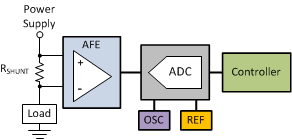
The remaining blocks in the signal path are selected based on how this measured current information is to be used by the system. There are several blocks that are common and found in most applications as shown in Figure 1-1. These blocks consist of an analog front end (AFE) to amplify a small signal from the sensor, an analog-to-digital converter (ADC) to digitize the amplified signal from the sensor, and a processor to allow for the sensor information to be analyzed so the system can respond accordingly to the measured current level.
 Figure 1-1 Current Sensing Signal Chain
One requirement for the AFE is allow for direct interface to the differential signal developed across the sense resistor. A single-ended output for the AFE simplifies the interface to the following ADC. Operational amplifiers in differential amplifier configurations are common for this functional requirement. Dedicated current sense amplifiers, INA210 for example, feature integrated gain setting components and are designed specifically for this type of application. The INA210 has the capability to accurately measure very small signals reducing the power dissipation requirement of the sensing resistor.
The next signal chain block is the ADC which is present to digitize the amplified sensor signal. This device can require additional external components (reference, oscillator) for more precise measurement capability. Similarly to the AFE, there are various options available for the ADC block. Stand-alone converters with the onboard references and oscillators are available as well as processors featuring onboard ADC channels.
Both integrated and discrete ADC blocks have their benefits as well as limitations. Fewer components on the board is one obvious advantage with the ADC being integrated into the processor. Existing instruction sets for the onboard ADC channels further reduces the requirement for additional software to be written to support a stand-alone ADC. However, silicon process nodes for digital controllers frequently are less optimized for precision analog, limiting the performance capability of the onboard converter. Discrete analog-to-digital converters have an advantage of allowing device selection based on optimized performance attributes such as resolution, noise or conversion speed.
A variation in this signal chain is to use an ADC to measure directly across the current sensing resistor eliminating the current sense amplifier entirely. A standard converter would have challenges in replacing the AFE and measuring the shunt voltage directly. One challenge is the large full-scale range of the ADC. Without the amplification of the sense resistor's voltage drop, either the full-range of the ADC cannot be fully utilized or a larger voltage drop will be needed across the resistor. A large voltage drop will result in a larger power dissipation across the sensing resistor. There are ADCs available with modified input ranges designed for measuring smaller signals directly which can allow for direct measurement of shunt voltages. An internal programmable gain amplifier (PGA) is typically integrated in these devices to leverage the full-scale range of the ADC.
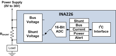
A limitation these small signal converters have is their limited common-mode input voltage range. These ADCs have input voltage ranges that are limited by their supply voltage which typically range from 3 V to 5.5 V based on the core processor voltage being supported. The INA226, shown in Figure 1-2, is a current sensing specific analog-to-digital converter that solves this common-mode limitation. This device features a 16-bit delta-sigma core and can monitor small differential shunt voltages on common-mode voltage rails as high as 36 V while being powered off a supply voltage that can range from 2.7 V to 5.5 V.
 Figure 1-2 INA226, Precision Current, Voltage, Power Sensing ADC
Similar to the ADCs with modified small input range capability, the INA226 has a full-scale input range of about 80 mV enabling the device to measure directly across the current sensing resistor. The INA226 has the ability to very accurately resolve small current variations with an LSB step size of 2.5 μV and a maximum input offset voltage of 10 μV. A 0.1-μV/°C offset drift ensures the measurement accuracy remains high with only an additional 12.5 μV of offset induced at temperatures as high as 125°C. A 0.1% maximum gain error also enables the measurement accuracy to remain high at the full-scale signal levels as well.
While the INA226 is able to accurately measure small shunt voltages this component has been designed with additional functionality useful for current sensing applications. This device features an internal register that is user-programmable with the specific value of the current sensing resistor that is present on the PCB. Having the value of the current sensing resistor allows the INA226 to directly convert the shunt voltage measured every conversion to the corresponding current value and stores this to an additional output register. The INA226 also features an internal multiplexer allowing the device to switch from a differential input measurement to a single ended voltage configuration to allow for measurement of the common-mode voltage directly. The voltage measurement, along with the previously measured shunt voltage and corresponding current calculation, allows the device the capability of computing power. The device stores this power calculation and provides this value along with the shunt voltage, current and common-mode voltage information to the processor over the two-wire serial bus.
In addition to the on-chip calculations of current and power, the INA226 features a programmable alert register that allows the device to compare each conversion value to a defined limit to determine if an out-of-range condition has occurred. This alert monitor can be configured to measure out-of-range conditions such as overcurrent, overvoltage, or overpower. The device also includes programmable signal averaging to further improve measurement accuracy.
The INA226 is optimized to support precision current measurements. The additional features included in this device provide the capability of supporting the signal management and monitoring needed in this current measurement function reducing the burden on the system processor.
Alternate Device Recommendations
For applications with lower performance requirements, using the INA234 still leverages the benefits of the dedicated current sensing analog-to-digital converter. For additional precision measurement capability where currents being measured are less than 15 A, the INA260 provides similar functionality to the INA226 while also featuring a precision 2-mΩ integrated current sensing resistor inside the package. For applications requiring significantly higher common-mode voltage capability, the AMC1305 provides onboard isolation and is capable of supporting working voltages as high as 1.5 kV DC and handling peak transients as high as 7 kV. For applications with lower performance requirements for the AFE, use the INA210 to take advantage of the benefits of a dedicated current sense amplifier.
| Device | Optimized Parameters | Performance Trade-Off |
|---|---|---|
| INA234 | Lower Cost | Higher VOS & Gain Error, Lower VCM Range |
| INA260 | Lower System Level Gain Error & Offset | Larger Package: TSSOP-16 |
| AMC1305 | Isolated Measurement, Higher Signal Bandwidth | Higher Cost, Higher VOS & Gain Error |
| INA210 | Lower Cost | Higher VOS & Gain Error |