This EVM user's guide describes the characteristics, operation, and use of the INA233EVM evaluation board. It discusses how to set up and configure the software and hardware, and reviews various aspects of the program operation. Throughout this document, the terms evaluation board, evaluation module, and EVM are synonymous with the INA233EVM. This EVM user's guide also includes information regarding operating procedures and input/output connections, an electrical schematic, printed circuit board (PCB) layout drawings, and a parts list for the EVM.
Windows® is a registered trademark of Microsoft.
All trademarks are the property of their respective owners.
The INA233 is a current shunt and power monitor with an I2C/SMBus/PMBus-compatible interface. The device monitors and reports values for current, power, and voltage. The integrated power accumulator can be used for energy or average power calculations. Programmable calibration value, conversion times, and averaging, combined with an internal multiplier, enable direct readouts of current in amperes and power in watts. The INA233EVM is a platform for evaluating the performance of the INA233 under various signal, shunt, and supply conditions.
This document gives a general overview of the INA233EVM, and provides a general description of the features and functions to be considered while using this evaluation module.
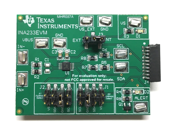
Table 1-1 summarizes the contents of the INA233EVM kit. Figure 1-1 shows all of the included hardware. Contact the Texas Instruments Product Information Center if any component is missing. TI also highly recommends checking the INA233 product folder on the TI web site at www.ti.com to update to the latest versions of the related software.
Item | Quantity |
---|---|
INA233EVM PCB Test Board | 1 |
SM-USB-DIG Platform PCB | 1 |
USB Extender Cable | 1 |
The following documents provide information regarding Texas Instruments integrated circuits used in the assembly of the INA233EVM. This EVM user's guide is available from the TI web site under literature number SBOU187. Any letter appended to the literature number corresponds to the document revision that is current at the time of the writing of this document. Newer revisions can be available from the TI web site. When ordering, identify the document by both title and literature number.
Figure 2-1 shows the overall system setup for the INA233EVM. The PC runs software that communicates with the SM-USB-DIG Platform. The SM-USB-DIG Platform generates the analog and digital signals used to communicate with the INA233 test board. Connectors on the INA233EVM test board allow the user to connect to the system under test conditions and monitor the power, current, and voltage.
Figure 2-2 depicts a block diagram of the INA233EVM PCB highlighting the power supplies, analog inputs, and digital I/O signals.
Table 2-1 lists the pinout for the 10-pin connector socket used to communicate between the INA233EVM and the SM-USB-DIG. It should be noted that the INA233EVM only uses the necessary I2C communication lines (pins 1 and 3) and the VS and GND pins (pin 6 and pin 8) to issue commands to the INA233 chip.
Pin on J4 | Signal | Description |
---|---|---|
1 | I2C_SCL | I2C Clock Signal (SCL) |
2 | CTRL/MEAS4 | GPIO: Control Output or Measure Input |
3 | I2C_SDA1 | I2C Data Signal (SDA) |
4 | CTRL/MEAS5 | GPIO: Control Output or Measure Input |
5 | SPI_DOUT1 | SPI Data Output (PICO) |
6 | VDUT | Switchable DUT Power Supply: +3.3 V, +5 V, Hi-Z (Disconnected)(1) |
7 | SPI_CLK | SPI Clock Signal (SCLK) |
8 | GND | Power Return (GND) |
9 | SPI_CS1 | SPI Chip Select Signal ( CS) |
10 | SPI_DIN1 | SPI Data Input (POCI) |
Figure 2-3 shows the block diagram for the SM-USB-DIG Platform. This platform is a general-purpose data acquisition system that is used on several different Texas Instruments evaluation modules. The details of its operation are included in a separate document, SBOU098 (available for download at www.ti.com). The block diagram shown in Figure 2-3 gives a brief overview of the platform. The primary control device on the SM-USB-DIG Platform is the TUSB3210. The TUSB3210 is an 8052 microcontroller that has an onboard USB interface. The microcontroller receives information from the host computer that it interprets into power, I2C, SPI, and other digital I/O patterns. During the digital I/O transaction, the microcontroller reads the response of any device connected to the I/O interface. The response from the device is sent back to the PC where it is interpreted by the host computer.
Setting up the INA233EVM involves the following sequence of operations:
Many of the components on the INA233EVM are susceptible to damage by electrostatic discharge (ESD). Customers are advised to observe proper ESD handling precautions when unpacking and handling the EVM, including the use of a grounded wrist strap at an approved ESD workstation.
This section discusses how to install the INA233EVM software.
The INA233EVM software must be installed on a computer running Windows® XP operating system or later. Windows 7 is the recommended operating system.
Make sure the hardware is not connected to the computer. Download the INA233EVM GUI from the INA233 Tools & Software folder. Extract the contents of the downloaded .zip file and run Setup_INA233EVM.exe. Follow the on-screen instructions provided in Figure 3-1 to complete the software installation.
Figure 3-2 shows the default jumper configuration for the INA233EVM. In general, the jumper settings of the SM-USB-DIG Platform do not need to be changed. Change the jumpers on the INA233EVM board to match your specific configuration. For example, set a specific I2C address by configuring J1 and J2.
Typically, jumper 3 (J3) on the INA233EVM is always set to the INT position. When set to the INT position, the SM-USB-DIG Platform provides the supply for the INA233. When this jumper is set to the EXT position, an external supply voltage can be connected to test point VS_EXT to provide the supply for the INA233.
Jumper 1 (J1) and jumper 2 (J2) control the I2C address pins for the INA233. These jumpers can set the address for A0 and A1 to either supply, ground, SCL, or SDA. Make sure to only connect one jumper at a time for each address control. Failure to properly connect jumpers can cause shorts or interruptions in the communication lines. For more information on the INA233 addressing, refer to the INA233 product data sheet.
Table 3-1 summarizes the function of the INA233 Test Board jumpers. For most applications, all jumpers must be left in the respective default configurations.
Jumper | Default | Purpose |
---|---|---|
J3 | INT | This jumper selects whether the VS pin on the INA233 is connected to the VDUT signal generated from the SM-USB-DIG Platform or whether the digital supply pin is connected to test point VS_EXT, allowing for an external supply to power the device. The default INT position connects the VS pin to the VDUT control signal. |
J1 | GND | This jumper selects the I2C A0 address selection for A0. |
J2 | GND | This jumper selects the I2C A1 address selection for A1. |
To set up the INA233EVM and connect the two PCBs of the EVM together (that is, the INA233 test board and SM-USB-DIG Platform board), gently slide the male and female ends of the 10-pin connectors together. Make sure that the two connectors are completely pushed together; loose connections can cause intermittent operation. Figure 3-3 show the proper orientation.
Lastly, connect the SM-USB-DIG to the computer, using the included USB extender cable. At this point the SM-USB-DIG powers on, but the EVM does not as shown in Figure 3-4. The power supply to the EVM must be enabled from the GUI.
Launch the INA233EVM GUI software. By default the Power button on the GUI is enabled so the VS LED on the EVM (D1) immediately lights up, indicating that the EVM PCB is receiving power, as shown Figure 3-5.
The INA233EVM software allows users to customize the board level voltage, regulated by the SM-USB DIG. By selecting either 3.3 V or 5 V, the user can designate which voltage the device operates at. The supply voltage (VDUT) is set to 3.3 V by default, but if necessary, the 5-V option can be selected, as shown in Figure 3-6.