SCDA033A April 2021 – April 2021 TMUX1108 , TMUX1136 , TMUX1308 , TS3A24159
1 Application Brief
Introduction
Modern pulse oximeters are requiring high levels of integration in a smaller size so that they are easy to hold, carry, and integrate. Their daily use requires a high-level of performance that can accurately measure heart rate and oxygen saturation levels in the blood in the finger tips.
The optical sensors in most consumer wearable devices use light signal to measure heart rate through a process called photoplethysmography (PPG). PPG involves shining light onto the surface of the skin, recording the variation in light intensity that is transmitted through the tissue as blood perfuses the superficial layers, and then using signal processing to convert the transmission variations into a heart rate. The right semiconductor components can help engineers, working on small-form-factor pulse oximeters, overcome key design challenges such as size constraints, current consumption, and low-current-leakage. Understanding the importance of these parameters can provide a peace of mind for the engineers and improve the standard of care for patients and consumers.
Measuring Heart Rate and Oxygen Saturation
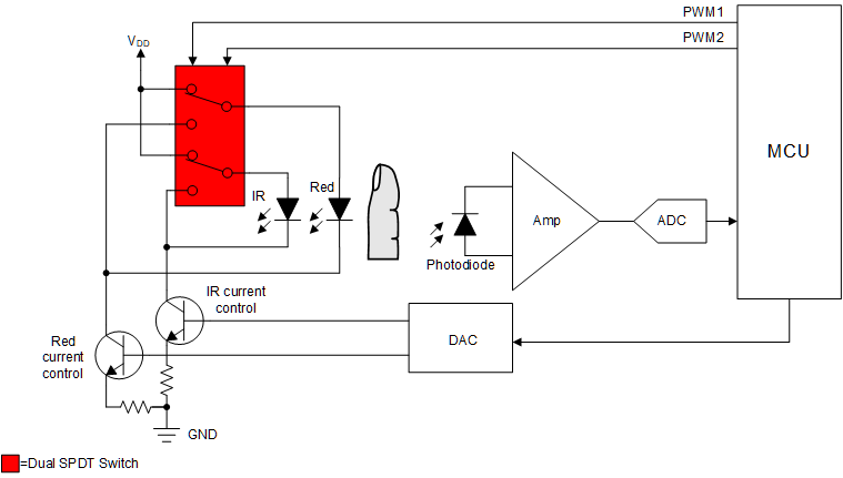
As highlighted above, a standard pulse oximeter uses PPG techniques to detect heart rate and measure the oxygen saturation (%SpO2) of a human’s blood based on the red light and infrared light absorption characteristics of oxygenated and deoxygenated hemoglobin. The pulse oximeter flashes red and infrared lights alternately through a finger to a photodiode. Infrared light gets absorbed by oxygenated hemoglobin while the red light passes through. Alternatively, deoxygenated hemoglobin allows infrared light to pass through and absorbs red light. The photodiode receives the non-absorbed light from each LED. This signal is conditioned using a trans-impedance amplifier, and Figure 1-1 shows the result, which represents the light that has been absorbed by the finger.
 Figure 1-1 Simplified Pulse Oximeter
Block Diagram
Figure 1-1 Simplified Pulse Oximeter
Block DiagramThe dual single-pull-double-through (SPDT) switch is used to turn on and off the infrared (IR) LED and the red LED through the control of pulse-width modulation (PWM) signals from the microcontroller (MCU). The photodiode is able to convert the light into an electrical signal after the red light and IR light pass through the finger, which is fed to the ADC to calculate %SpO2. The dual SPDT switch needs to have low on-resistance (RON) to limit voltage drops across the switch. The TS3A24159 (a 2:1, 2-channel multiplexer) has a typical power consumption level less than 0.001 µW. This can help extend the device battery lifetime of pulse oximeters, and allow a peace of mind that these devices work when they are needed the most.
Increasing Accuracy and Precision
The human body varies between each person based on skin thickness and pigmentation, which may cause pulse oximeters to have limitations and risk inaccuracy under certain circumstances. Increasing the number of LEDs with varying wavelengths for different levels of penetration and improved accuracy is one way to overcome this limitation. It is more difficult to maintain small size and minimize additional cost for the added accuracy of the pulse oximeter as the number of LEDs are added to the solution.
A multiplexer can be used to eliminate the need for investing in a larger, pricier MCU or extra buffers, and may save system solution size and complexity. Similarly, increasing the number of photodiodes with a multiplexer is a beneficial and cost-effective way to improve the performance of your pulse oximeters. The amount of these signals that an MCU can register is limited by the number of input and output (IO) pins incorporated in their architecture. In a scenario where an MCU has only a single ADC input available, but 4 sensing elements that require monitoring, the input count would fall 3 sensing elements short of the system requirements. The TMUX1308, an 8:1, 1-channel multiplexer with leakage current of 1 nA (typical), housed in the industry’s smallest leaded package, can be used to expand the IO pins around the MCU.
As the number of LEDs and photodiodes are increased, ensuring that the other adjacent diodes do not turn on or receive the incorrect optical wavelength, is critical in preventing misreading. When the MCU is switching between the varying diodes, the TMUX1111 (a 1:1, 4-channel multiplexer with typical leakage current of 3 pA) can help ensure other diodes do not turn on incorrectly throughout the LED flashing cycle.
Accounting for the Varying Optical Wavelengths
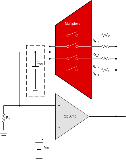
The reflected light varies between individuals, and the amplitude needs to change dynamically before reaching the ADC and MCU. One way to configure the signal is to change the amplification of the signal by creating a discrete programmable gain amplifier through a multiplexer, resistors, and an operational amplifier. The multiplexer switches between different resistance values, which in turn, allows for different gain values from the same operational amplifier. In Figure 1-2, incorporating a 4-to-1 one-channel multiplexer, such as the TMUX1104 can be used with feedback resistors to change the gain value.
 Figure 1-2 Circuit Model of a Basic
Discrete Programmable Gain Amplifier
Figure 1-2 Circuit Model of a Basic
Discrete Programmable Gain AmplifierSummary
Higher levels of integration and performance, while maintaining the same or smaller size within pulse oximeters, are becoming a theme with each design cycle. Some pulse oximeters may not require the pricier MCUs or analog front-ends that include the extra IO pins to support extra sensors, but rather seek other innovative ways to implement performance improvements. A multiplexer can be the key in saving in bill of material (BOM) costs and improving accuracy without compromising solution size.