SLAAE53 July 2022 MSP430FR4133
1 Application Brief
Introduction
Liquid crystal display (LCD) is widely used in many display applications and is often configured by complex segments depending on specific kinds of LCDs. This demonstration uses a 4-mux LCD -- FH-1138P which displays six full alpha-numeric characters in addition to several symbols at the top. The MSP430FR4133 microcontroller (MCU) has flexible LCD pins allowing any pin to be a SEG or a COM. As a result, this allows an optimal memory setting for software, along with a simple layout on the PCB. This demonstration uses the MSP430FR4133 device and at the same time configures the GUI to control the FH-138P to act as a stopwatch or character display.
Implementation
This application uses a 4-mux LCD with 108 individually addressable LCD segments to co-work with GUI as two functions:
- Stopwatch time display
- Alphanumeric character display
Figure 1-1 shows the block diagram of stopwatch block and character display.
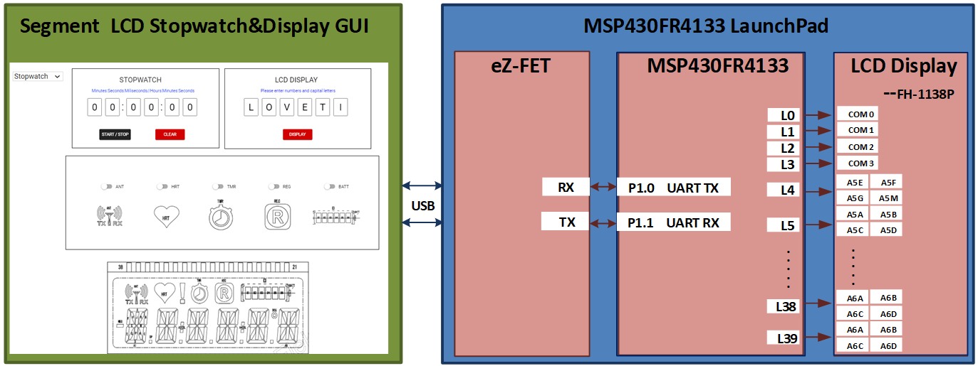 Figure 1-1 Implementation
Overview
Figure 1-1 Implementation
OverviewIn stopwatch mode, the MCU measures the time using the internal RTC module and used the specific LCD drive pins to display time in the LCD. There are two buttons in the GUI to control the time: one is to start or stop the stopwatch, and the other is to clear the timer. UART is used to communicate between MSP430FR4133 and GUI in the PC.
In display mode, there are six input boxes reserved in GUI that can input alphanumeric or letters and once the display button is pressed, the system will go into display mode and then the LCD will show the contents the same as input in the GUI. FH-1138P is a 4-mux LCD as shown in Figure 1-2 and then four COM pins are needed from the MSP430FR4133. With four COM pins, each segment pin controls four bits or segments. As a result, each alphanumeric character A1 to A6 is controlled by four pins and two adjacent registers of the device, as shown in Figure 1-1. It is obvious that the specific LCD drive pins of MSP430FR4133 ease the software setting of LCD and at the same time simplify the layout.
To show the other symbols at the top of LCD, there are also five switch buttons in GUI to control the display of specific symbols such as HRT/TNR/REC as shown in Figure 1-2.
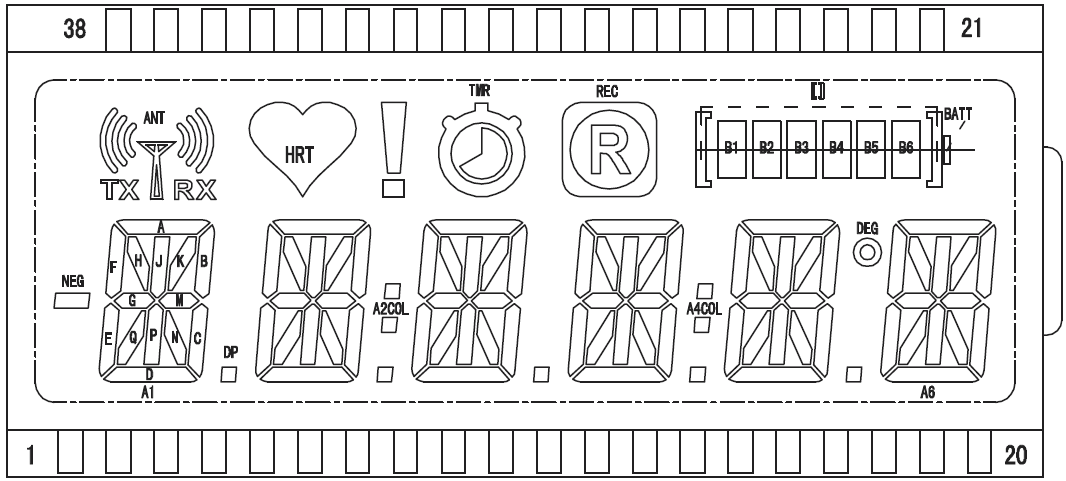 Figure 1-2 LCD Segment Layout
The MSP430FR4133 LaunchPad™ Development Kit (shown in Figure 1-3) is used in this example, and contains everything needed to start developing on the MSP430™ ultra-low-power (ULP) FRAM-based microcontroller (MCU) platform. This LaunchPad consists of three parts including on-board debugger named eZ-FET, MSP430FR4133 and segment LCD named FH-1138P. The eZ-FET is used for programming, debugging, and energy measurements and backchannel USB-to-UART on eZ-FET is used for UART communication with the GUI. The receive and transmit pins are assigned to P1.1 and P1.0. There are 60 available pins that can be configured as general purpose I/O and 32 of these are used in this example to control the COMs and SEGs of LCD to display characters and symbols.
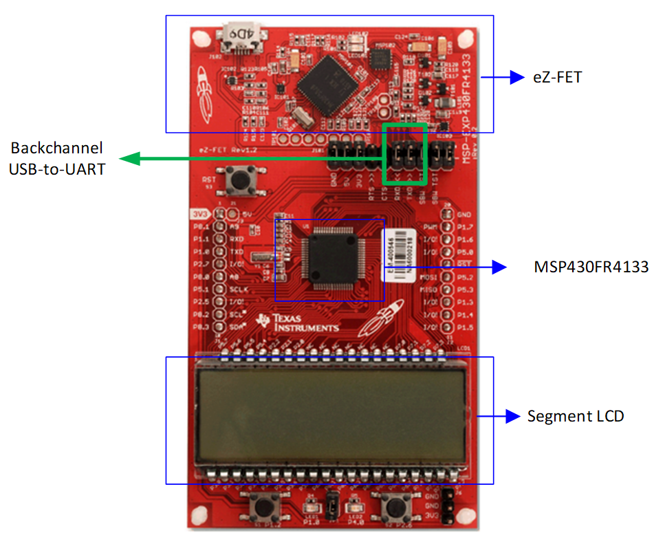 Figure 1-3 MSP430FR4133 LaunchPad and
Connections
Figure 1-3 MSP430FR4133 LaunchPad and
ConnectionsThe LaunchPad can be powered by two methods including on-board eZ-FET and external power. The most common power-supply scenario is from USB through the eZ-FET debugger. Firstly, the original 5 V is powered from the USB port and then regulates to 3.3 V for eZ-FET operation and the other 3.3 V to the target side of the LaunchPad. Power from the eZ-FET is controlled by jumper J101 and Header J6 is present on the board to supply external power directly.
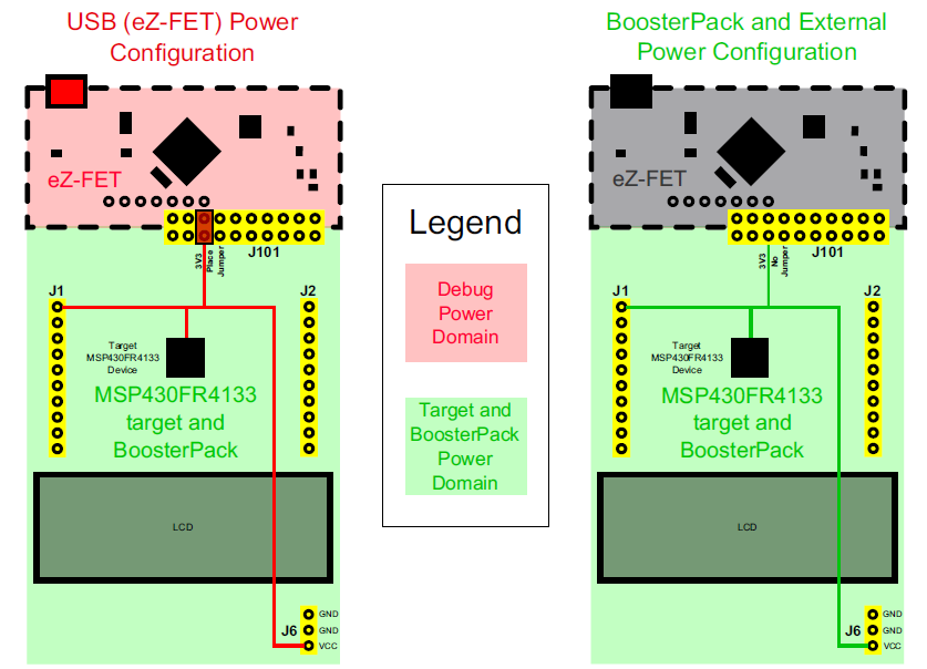 Figure 1-4 MSP430FR4133 Power Block
Diagram
Figure 1-4 MSP430FR4133 Power Block
DiagramPerformance
As shown in Figure 1-5, it shows the LCD stopwatch and display GUI that includes a drop-down menu to select LCD stopwatch mode or display mode. Display mode allows you to enter six characters (including numbers and capital letters) and transfer these contents to LCD at the same time. The toggle button can be clicked individually to show the other additional symbols in LCD without erasing the original content in LCD.
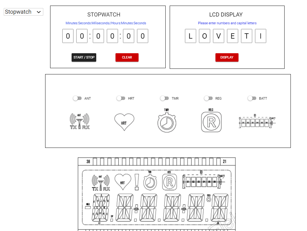 Figure 1-5 LCD Stopwatch and Display
GUI
Figure 1-5 LCD Stopwatch and Display
GUIFrom coding side, it is necessary to configure the register to display any number from 0 to 9 and any capital letters from A to Z at any port which can be found in example codes.
When powered up, the device goes into start up mode. The LCD scrolls the display ‘PLEASE SELECT MODES’ and the system waits for the selection of stopwatch mode or display mode.
For stop watch mode, RTC module plays a very important role in this function. And because FH-1138P can display six characters simultaneously, the LCD can display milliseconds, seconds, minutes and hours. The LCD displays ‘minutes: seconds: milliseconds’ at start and when the time reaches an hour, the LCD turns to display ‘hours: minutes: seconds’. Once the ‘stop watch mode’ is selected from GUI, the timer can be started, stopped or cleared by the buttons in the GUI. When the ‘start’ button is pressed, the RTC starts to count and displays the time in GUI and LCD simultaneously. Similarly, when the button is clicked again, the stop command is sent out and the RTC stops to count. If the button is clicked again, the button function switches back to start function again to continue the timer move on. The clear button can reset back to the original state ‘00:00:00’. RTC is initialized to interrupt every 0.1 seconds. When RTC interrupt occurs, the time is updated and uploaded to the GUI and output to the displayer.
On the other hand, once the display mode is selected, the LCD scrolls display ‘DISPLAY MODE’ and wait for the input of six characters from GUI. When the input is finished, and the button ‘Display’ is pressed, the content shows in LCD.
A summary of the software flowchart and GUI flow is shown in Figure 1-6.
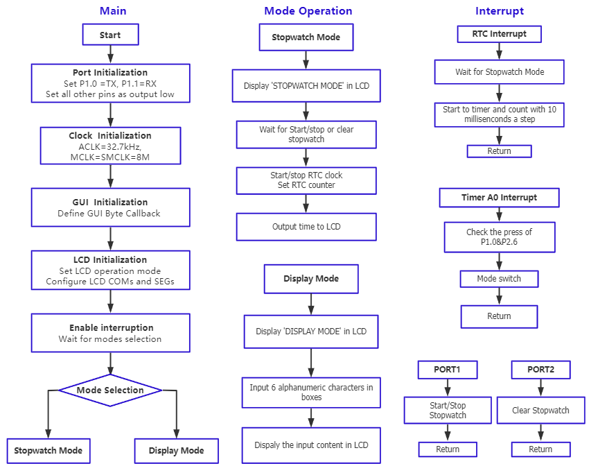 Figure 1-6 Software Flowchart for Segment
LCD Stopwatch and Display
Figure 1-6 Software Flowchart for Segment
LCD Stopwatch and DisplayTo Get Started
- Watch our training video “LCD Stopwatch & Display”, where you work through how to use the MSP430FR4133 as a stopwatch as well as a character display.
- Order a MSP430FR4133 LaunchPad kit to evaluate the LCD Stopwatch and Display example Code.
- Download and test this example with the LCD Stopwatch and Display example GUI, where you can use the MCU as a stopwatch and output characters to the display.
- Evaluate the LCD Stopwatch and Display example code for the MSP430FR4133 LaunchPad kit.
| Part Number | Key Features |
|---|---|
| MSP430FR4133 | 15KB FRAM, 2KB SRAM, 10-bit ADC, UART/SPI/I2C, Timer |
| MSP430FR4132 | 8KB FRAM, 1KB SRAM, 10-bit ADC, UART/SPI/I2C, Timer |
| MSP430FR4131 | 4KB FRAM, 512B SRAM, 10-bit ADC, UART/SPI/I2C, Timer |