SLLA417B August 2018 – May 2021 ISO1640 , ISO1640-Q1 , ISO1641 , ISO7731 , ISO7742 , ISOW7740 , ISOW7741 , ISOW7742 , ISOW7743 , ISOW7744 , ISOW7821 , ISOW7840 , ISOW7841 , ISOW7843 , ISOW7844 , SN6501 , SN6501-Q1 , SN6505A , SN6505B
1 TI Tech Note
Inter-integrated circuit (I2C) bus communication is a two wire half duplex method for communication over short distances and has been widely adopted for a variety of applications because of its simplicity. In systems where the I2C bus is used to communicate between two domains of different potentials or where high voltages are present, galvanic isolation can be used to protect circuitry and human operators as well as break ground loops that can create noise that will interfere with signal communication.
Since digital isolators are inherently unidirectional, implementing the bidirectional communication of the I2C bus presents numerous challenges for system designers. This document will address the different methods available to isolate the I2C bus and how to provide isolated power for these solutions.
Signal Isolation
Signal isolation for the I2C bus can be achieved with two methods. The first method is to use a digital isolator with external circuitry to separate the bidirectional data path into two unidirectional channels. After the bidirectional data is separated into unidirectional signals, the digital isolator will modulate the input signal for each channel and pass the signal across the isolation barrier before demodulating the signal at the output. The Designing a reinforced isolated I2C-Bus interface by using digital isolators application note explains in more detail the design considerations and methodology for separating the bidirectional I2C signals into unidirectional signals to interface with the digital isolator.
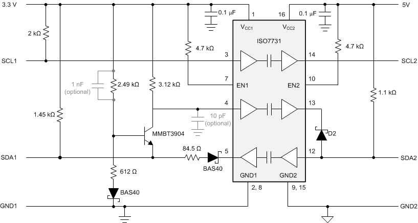
 Figure 1-1 Discrete Implementation for Isolated I2C With a Digital Isolator
Figure 1-1 shows the implementation of this method in an application with bidirectional data and unidirectional clock using a three channel digital isolator such as the ISO6731 or ISO7731. For multi-master systems requiring bidirectional data and clock signals, the same methods explained in the application note can be used with a four channel digital isolator such as the ISO6742 or ISO7742.
The second method for isolating the I2C bus is to use an integrated solution such as the ISO164x family of devices. These integrated solutions use internal circuitry combined with the digital isolator to achieve the same isolated I2C buffer functionality. The ISO1640 is designed for multi-master systems with bidirectional data and clock signals and the ISO1641 is designed for systems with bidirectional data and unidirectional clock. If an application with bidirectional data and unidirectional clock requires clock stretching function, it is recommended to use ISO1640 to achieve clock stretching.
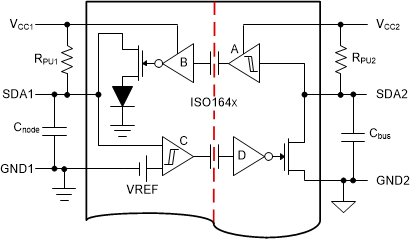
 Figure 1-2 ISO164x Method for Separating the Bidirectional SDA Signal Into Unidirectional Isolation Channels
Figure 1-2 shows a functional diagram of how the bidirectional serial data line (SDA) signal from the I2C bus is internally separated into two unidirectional signals that are isolated using the channels of the digital isolator. The isolated I2C devices are designed to interface with a low capacitance I2C node on side 1 and a fully loaded I2C bus with up to 400 pF on side 2. The arrangement and connection of internal unidirectional channels creates a closed signal loop that is prone to latch-up. This latch-up condition is prevented by implementing an output buffer (B) whose output low-level is raised by a diode drop to approximately 0.65 V, and the input buffer (C) that consists of a comparator with defined hysteresis. The comparator's upper and lower input thresholds then distinguish between the low potential from SDA1 and the potential from output buffer B.
Each solution for isolating the signal in an I2C system will have trade-offs. The discrete solution using a digital isolator provides more freedom in part selection with the ISO6731, ISO6742, ISO7731 or ISO7742 both available in multiple package options with different isolation ratings to fit the specific use case; however, this solution also has the drawback of needing external circuitry that occupies more board space . The integrated solution with ISO1640 or ISO1641 will occupy less board space and require less design efforts than the discrete solution, but is only available in limited package and isolation rating options.
Power Isolation
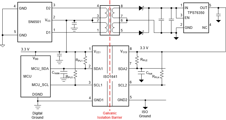
Regardless of the method chosen to isolate the I2C signal, an isolated power supply will be required to power the secondary side of the digital isolator or isolated I2C buffer. The first solution for providing isolated power is to use a circuit similar to Figure 1-3, which uses the SN6501 transformer driver to drive a transformer in a push pull configuration. The benefit of this solution is that it provides greater than 80% efficiency and the transformer and LDO can be selected to optimize for specific design considerations. The SN6501 provides up to 1.5 W of power and can be replaced with the SN6505 for up to 5 W if isolated power is needed for additional devices.
 Figure 1-3 Isolated I2C Solution for Signal and Power With ISO1641
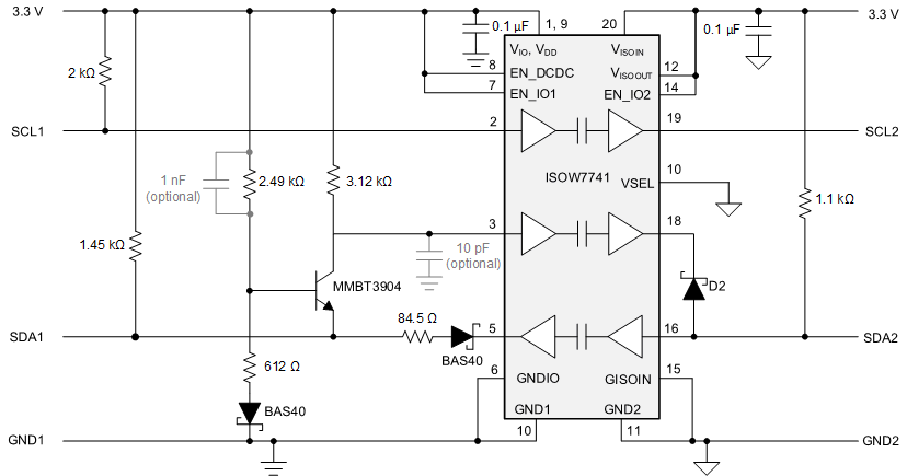
The second solution for providing isolated power in the I2C system is to replace the digital isolator in the discrete approach to signal isolation solution with ISOW7741. The ISOW7741 device is a digital isolator with integrated signal and power isolation in a 16 pin SOIC package. The advantage of this device is that it greatly reduces board space by integrating the transformer, transformer driver, and LDO. The small solution size comes with a trade off in efficiency as the transformer integrated into the chip provides a typical efficiency of around 45% and can provide up to 500 mW of isolated power. With the integrated power solution, since the transformers are smaller in size, switching frequencies are higher, leading to higher emissions as compared to the discrete solution. Figure 1-4 shows the implementation of ISOW7741 in a system with bidirectional data and a unidirectional clock. The same methodology used to separate the SDA signal can be applied to the clock signal if bidirectional clock is needed.
 Figure 1-4 Isolated I2C Solution for Signal and Power Using ISOW7741
Conclusion
There are many methods to isolate signal and power for an I2C system and the correct choice will depend on the specific application requirements. Isolated I2C buffers such as the ISO164x family make design easy by integrating all of the external circuitry needed to isolate the SDA and SCL signals while preventing latch up and complying with the I2C standard. In some cases, it may be beneficial to have the flexibility of numerous packages and isolation ratings available. A discrete solution using the ISO77xx series of digital isolators offers this flexibility and can still achieve the same isolated I2C functionality as the integrated solution, when designed correctly.
For isolated power the key trade-off is efficiency versus board space. The SN6501 solution provides a compact, low noise, and high efficiency solution for generating isolated power. For applications where further board space reduction is desired, the ISOW7741 solution simplifies design and reduces board space compared to the first solution. A system designer must weigh the trade-offs of each solution for isolating signal and power in an isolated I2C system to determine the best fit for their particular application.