SLLSEP2D August 2015 – May 2017 TUSB320HI , TUSB320LI
PRODUCTION DATA.
- 1 Features
- 2 Applications
- 3 Description
- 4 Revision History
- 5 Pin Configuration and Functions
- 6 Specifications
- 7 Detailed Description
- 8 Application and Implementation
- 9 Power Supply Recommendations
- 10Layout
- 11Device and Documentation Support
- 12Mechanical, Packaging, and Orderable Information
Package Options
Mechanical Data (Package|Pins)
- RWB|12
Thermal pad, mechanical data (Package|Pins)
Orderable Information
1 Features
- USB Type-C™ Specification 1.1
- Backward Compatible with USB Type-C Specification 1.0
- Supports Up to 3 A of Current Advertisement and Detection
- Mode Configuration
- Host Only – DFP (Source)
- Device Only – UFP (Sink)
- Dual Role Port – DRP
- Supports both Try.SRC and Try.SNK
- Channel Configuration (CC)
- Attach of USB Port Detection
- Cable Orientation Detection
- Role Detection
- Type-C Current Mode (Default, Medium, High)
- VBUS Detection
- I2C or GPIO Control
- Role Configuration Control Through I2C
- Supply Voltage: 2.7 V to 5 V
- Low Current Consumption
- Industrial Temperature Range of –40 to 85°C
2 Applications
- Host, Device, Dual Role Port Applications
- Mobile Phones
- Tablets and Notebooks
- USB Peripherals
3 Description
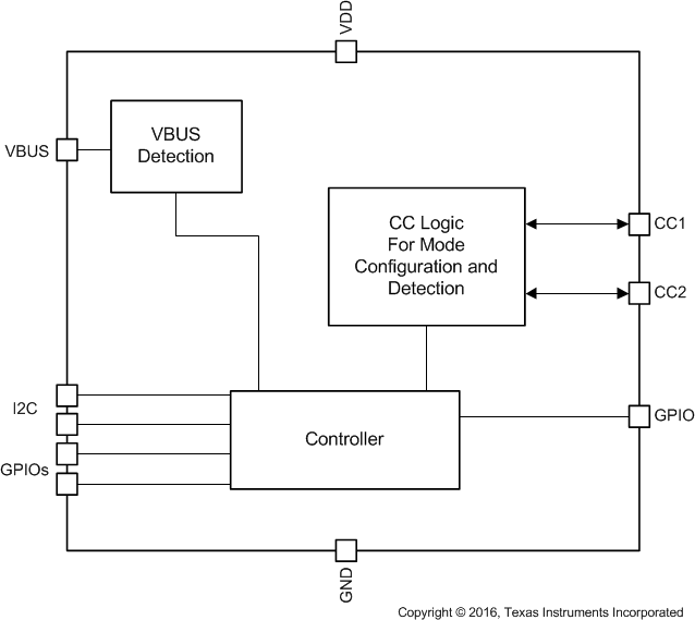
The TUSB320LI and TUSB320HI devices (remainder of this document called TUSB320 unless otherwise noted) enables USB Type-C ports with the configuration channel (CC) logic needed for Type-C ecosystems. The TUSB320 devices use the CC pins to determine port attach and detach, cable orientation, role detection, and port control for Type-C current mode. The TUSB320 devices can be configured as a downstream facing port (DFP), upstream facing port (UFP) or a dual role port (DRP) making it ideal for any application.
The TUSB320 devices alternate configuration as a DFP or UFP according to the Type-C specifications. The CC logic block monitors the CC1 and CC2 pins for pullup or pulldown resistances to determine when a USB port has been attached, the orientation of the cable, and the role detected. The CC logic detects the Type-C current mode as default, medium, or high depending on the role detected. VBUS detection is implemented to determine a successful attach in UFP and DRP modes.
The devices operate over a wide supply range and have low-power consumption. The TUSB320 is available in two versions of enable: Active low enable called TUSB320LI and active high enable called TUSB320HI. The TUSB320 family of devices are available in industrial temperature ranges.
Device Information(1)
| PART NUMBER | PACKAGE | BODY SIZE (NOM) |
|---|---|---|
| TUSB320HI | X2QFN (12) | 1.60 mm × 1.60 mm |
| TUSB320LI | X2QFN (12) | 1.60 mm × 1.60 mm |
- For all available packages, see the orderable addendum at the end of the data sheet.
Simplified Schematic

Sample Applications
