ZHCSE02C March   2011  – March 2015 DP83848Q-Q1

PRODUCTION DATA.  

  1. 器件概述
    1. 1.1 特性
    2. 1.2 应用范围
    3. 1.3 说明
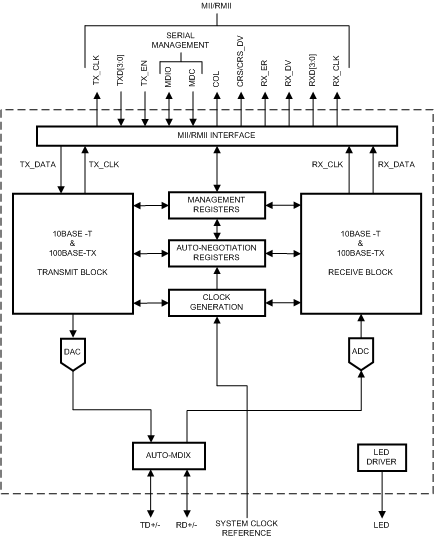
    4. 1.4 功能框图
  2. 修订历史记录
  3. Pin Configuration and Functions
    1. 3.1  Pin Layout
    2. 3.2  Package Pin Assignments
    3. 3.3  Serial Management Interface
    4. 3.4  MAC Data Interface
    5. 3.5  Clock Interface
    6. 3.6  LED Interface
    7. 3.7  RESET
    8. 3.8  Strap Options
    9. 3.9  10 Mb/s and 100 Mb/s PMD Interface
    10. 3.10 Special Connections
    11. 3.11 Power Supply Pins
  4. Specifications
    1. 4.1 Absolute Maximum Ratings
    2. 4.2 ESD Ratings
    3. 4.3 Recommended Operating Conditions
    4. 4.4 Thermal Information
    5. 4.5 Electrical Characteristics: DC
    6. 4.6 Electrical Characteristics: AC
  5. Detailed Description
    1. 5.1 Overview
    2. 5.2 Functional Block Diagram
    3. 5.3 Feature Description
      1. 5.3.1 Auto-Negotiation
        1. 5.3.1.1 Auto-Negotiation Pin Control
        2. 5.3.1.2 Auto-Negotiation Register Control
        3. 5.3.1.3 Auto-Negotiation Parallel Detection
        4. 5.3.1.4 Auto-Negotiation Restart
        5. 5.3.1.5 Enabling Auto-Negotiation via Software
        6. 5.3.1.6 Auto-Negotiation Complete Time
      2. 5.3.2 Auto-MDIX
      3. 5.3.3 LED Interface
        1. 5.3.3.1 LEDs
        2. 5.3.3.2 LED Direct Control
      4. 5.3.4 Internal Loopback
      5. 5.3.5 BIST
      6. 5.3.6 Energy Detect Mode
    4. 5.4 Device Functional Modes
      1. 5.4.1 MII Interface
        1. 5.4.1.1 Nibble-wide MII Data Interface
        2. 5.4.1.2 Collision Detect
        3. 5.4.1.3 Carrier Sense
      2. 5.4.2 Reduced MII Interface
      3. 5.4.3 802.3u MII Serial Management Interface
        1. 5.4.3.1 Serial Management Register Access
        2. 5.4.3.2 Serial Management Access Protocol
        3. 5.4.3.3 Serial Management Preamble Suppression
      4. 5.4.4 PHY Address
        1. 5.4.4.1 MII Isolate Mode
      5. 5.4.5 Half Duplex vs. Full Duplex
      6. 5.4.6 Reset Operation
        1. 5.4.6.1 Hardware Reset
        2. 5.4.6.2 Software Reset
    5. 5.5 Programming
      1. 5.5.1 Architecture
        1. 5.5.1.1 100BASE-TX Transmitter
          1. 5.5.1.1.1 Code-Group Encoding and Injection
          2. 5.5.1.1.2 Scrambler
          3. 5.5.1.1.3 NRZ to NRZI Encoder
          4. 5.5.1.1.4 Binary to MLT-3 Convertor
        2. 5.5.1.2 100BASE-TX Receiver
          1. 5.5.1.2.1  Analog Front End
          2. 5.5.1.2.2  Digital Signal Processor
            1. 5.5.1.2.2.1 Digital Adaptive Equalization and Gain Control
            2. 5.5.1.2.2.2 Base Line Wander Compensation
          3. 5.5.1.2.3  Signal Detect
          4. 5.5.1.2.4  MLT-3 to NRZI Decoder
          5. 5.5.1.2.5  NRZI to NRZ
          6. 5.5.1.2.6  Serial to Parallel
          7. 5.5.1.2.7  Descrambler
          8. 5.5.1.2.8  Code-group Alignment
          9. 5.5.1.2.9  4B/5B Decoder
          10. 5.5.1.2.10 100BASE-TX Link Integrity Monitor
          11. 5.5.1.2.11 Bad SSD Detection
        3. 5.5.1.3 10BASE-T Transceiver Module
          1. 5.5.1.3.1  Operational Modes
            1. 5.5.1.3.1.1 Half Duplex Mode
            2. 5.5.1.3.1.2 Full Duplex Mode
          2. 5.5.1.3.2  Smart Squelch
          3. 5.5.1.3.3  Collision Detection and SQE
          4. 5.5.1.3.4  Carrier Sense
          5. 5.5.1.3.5  Normal Link Pulse Detection and Generation
          6. 5.5.1.3.6  Jabber Function
          7. 5.5.1.3.7  Automatic Link Polarity Detection and Correction
          8. 5.5.1.3.8  Transmit and Receive Filtering
          9. 5.5.1.3.9  Transmitter
          10. 5.5.1.3.10 Receiver
    6. 5.6 Memory
      1. 5.6.1 Register Definition
        1. 5.6.1.1 Basic Mode Control Register (BMCR)
        2. 5.6.1.2 Basic Mode Status Register (BMSR)
        3. 5.6.1.3 PHY Identifier Register #1 (PHYIDR1)
        4. 5.6.1.4 PHY Identifier Register #2 (PHYIDR2)
        5. 5.6.1.5 Auto-Negotiation Advertisement Register (ANAR)
        6. 5.6.1.6 Auto-Negotiation Link Partner Ability Register (ANLPAR) (BASE Page)
        7. 5.6.1.7 Auto-Negotiation Link Partner Ability Register (ANLPAR) (Next Page)
        8. 5.6.1.8 Auto-Negotiate Expansion Register (ANER)
        9. 5.6.1.9 Auto-Negotiation Next Page Transmit Register (ANNPTR)
      2. 5.6.2 Extended Registers
        1. 5.6.2.1  PHY Status Register (PHYSTS)
        2. 5.6.2.2  False Carrier Sense Counter Register (FCSCR)
        3. 5.6.2.3  Receiver Error Counter Register (RECR)
        4. 5.6.2.4  100 Mb/s PCS Configuration and Status Register (PCSR)
        5. 5.6.2.5  RMII and Bypass Register (RBR)
        6. 5.6.2.6  LED Direct Control Register (LEDCR)
        7. 5.6.2.7  PHY Control Register (PHYCR)
        8. 5.6.2.8  10 Base-T Status/Control Register (10BTSCR)
        9. 5.6.2.9  CD Test and BIST Extensions Register (CDCTRL1)
        10. 5.6.2.10 Energy Detect Control (EDCR)
  6. Application and Implementation
    1. 6.1 Application Information
    2. 6.2 Typical Application
      1. 6.2.1 Design Requirements
        1. 6.2.1.1 TPI Network Circuit
        2. 6.2.1.2 Clock IN (X1) Requirements
        3. 6.2.1.3 Power Feedback Circuit
        4. 6.2.1.4 Magnetics
      2. 6.2.2 Detailed Design Procedure
        1. 6.2.2.1 MAC Interface (MII/RMII)
        2. 6.2.2.2 Termination Requirement
        3. 6.2.2.3 Recommended Maximum Trace Length
        4. 6.2.2.4 Calculating Impedance
      3. 6.2.3 Application Curve
  7. Power Supply Recommendations
  8. Layout
    1. 8.1 Layout Guidelines
      1. 8.1.1 PCB Layout Considerations
      2. 8.1.2 PCB Layer Stacking
    2. 8.2 Layout Example
  9. 器件和文档支持
    1. 9.1 文档支持
      1. 9.1.1 相关文档
    2. 9.2 商标
    3. 9.3 静电放电警告
    4. 9.4 术语表
  10. 10机械、封装和可订购信息

封装选项

机械数据 (封装 | 引脚)
散热焊盘机械数据 (封装 | 引脚)
订购信息

器件概述

特性

  • AEC-Q100 等级 2
  • 极端温度范围:–40°C 至 105°C
  • 低功耗 3.3V,0.18µm CMOS 技术
  • 低功耗:小于 270mW(典型值)
  • 3.3V MAC 接口
  • 针对 10/100Mb/s 的自动 MDIX
  • 能量检测模式
  • 25MHz 时钟输出
  • RMII 修订版本 1.2 接口(可配置)
  • MII 串行管理接口(MDC 和 MDIO)
  • IEEE 802.3u MII
  • IEEE 802.3u 自动协商和并行检测
  • IEEE 802.3u ENDEC,10BASE-T 收发器和滤波器
  • IEEE 802.3u PCS,100BASE-TX 收发器和滤波器
  • 集成了符合 ANSI X3.263 标准的双绞线物理介质相关 (TP-PMD) 物理子层,该子层具有自适应均衡和基线漂移补偿
  • 长达 150 米的无故障运行
  • 用于链路和活动的可编程 LED 支持
  • 针对完整 PHY 状态的单寄存器访问
  • 10/100Mb/s 数据包 BIST(内置自检)

应用范围

  • 汽车和运输
  • 工业控制和工厂自动化
  • 通用嵌入式 应用

说明

随着需要以太网连接的 应用 数量不断增多,使支持以太网的设备进入到更恶劣的环境中。

DP83848Q-Q1 具有超出典型工业温度范围的扩展温度性能,旨在克服这些新型 应用 面临的挑战。 DP83848Q-Q1 是一款高度可靠、功能丰富、性能强大的器件,可在 –40°C 至 105°C 的扩展温度范围内满足 IEEE 802.3u 标准。此器件非常适合汽车和交通工具、无线远程基站和工业控制 应用等恶劣环境。

此器件提供增强的 ESD 保护以及 MII 或 RMII 接口选择,从而在 MPU 选择方面实现最大的灵活性;所有这些特性都融入于一个 40 引脚的 WQFN 封装中。

DP83848Q-Q1 具有在较宽的工作温度范围,强化了 PHYTER™系列器件的领先地位。TI 的 PHYTER 收发器产品线基于数十载的以太网专业经验,提供的高性能和灵活性可让最终用户轻松进行定制的实施方案以满足这些应用需求。

器件信息(1)

器件型号 封装 封装尺寸(标称值)
DP83848Q-Q1 WQFN (40) 6.00mm × 6.00mm
如需了解所有可用封装,请参阅数据表末尾的可订购产品附录。

功能框图

DP83848Q-Q1 30152501.gif