ZHCSCQ0 August   2014 TPS25921A , TPS25921L

PRODUCTION DATA.  

  1. 特性
  2. 应用范围
  3. 说明
  4. 应用电路原理图
  5. 修订历史记录
  6. Pin Configuration and Functions
  7. Specifications
    1. 7.1 Absolute Maximum Ratings
    2. 7.2 Handling Ratings
    3. 7.3 Recommended Operating Conditions
    4. 7.4 Thermal Characteristics
    5. 7.5 Electrical Characteristics
    6. 7.6 Timing Requirements
    7. 7.7 Typical Characteristics
  8. Parametric Measurement Information
  9. Detailed Description
    1. 9.1 Overview
    2. 9.2 Functional Block Diagram
    3. 9.3 Feature Description
      1. 9.3.1 Enable and Adjusting Undervoltage Lockout (UVLO)
      2. 9.3.2 Overvoltage Protection (OVP)
      3. 9.3.3 Hot Plug-in and In-Rush Current Control
      4. 9.3.4 Overload and Short Circuit Protection :
        1. 9.3.4.1 Overload Protection
        2. 9.3.4.2 Short Circuit Protection
        3. 9.3.4.3 Start-Up with Short on Output
        4. 9.3.4.4 Constant Current Limit Behavior during Overcurrent Faults
      5. 9.3.5 FAULT Response
      6. 9.3.6 IN, OUT and GND Pins
      7. 9.3.7 Thermal Shutdown:
    4. 9.4 Device Functional Modes
      1. 9.4.1 Shutdown Control
      2. 9.4.2 Operational Overview of Device Functions
  10. 10Applications and Implementation
    1. 10.1 Application Information
    2. 10.2 Typical Application
      1. 10.2.1 Precision Current Limiting and Protection for White Goods
        1. 10.2.1.1 Design Requirements
        2. 10.2.1.2 Detailed Design Procedure
          1. 10.2.1.2.1 Step by Step Design Procedure
          2. 10.2.1.2.2 Programming the Current-Limit Threshold: R(ILIM) Selection
          3. 10.2.1.2.3 Undervoltage Lockout and Overvoltage Set Point
          4. 10.2.1.2.4 Setting Output Voltage Ramp time (tSS)
            1. 10.2.1.2.4.1 Case1: Start-up Without Load: Only Output Capacitance C(OUT) Draws Current During Start-up
            2. 10.2.1.2.4.2 Case 2: Start-up With Load: Output Capacitance C(OUT) and Load Draws Current During Start-up
          5. 10.2.1.2.5 Support Component Selections - R4 and CIN
        3. 10.2.1.3 Application Curves
  11. 11System Examples
    1. 11.1 Protection and Current Limiting for Primary-Side Regulated Power Supplies
    2. 11.2 Precision Current Limiting in Intrinsic Safety Applications
    3. 11.3 Smart Load Switch
  12. 12Power Supply Recommendations
    1. 12.1 Transient Protection
    2. 12.2 Output Short-Circuit Measurements
  13. 13Layout
    1. 13.1 Layout Guidelines
    2. 13.2 Layout Example
  14. 14器件和文档支持
    1. 14.1 相关链接
    2. 14.2 Trademarks
    3. 14.3 Electrostatic Discharge Caution
    4. 14.4 术语表
  15. 15机械封装和可订购信息

封装选项

机械数据 (封装 | 引脚)
散热焊盘机械数据 (封装 | 引脚)
订购信息

1 特性

  • 4.5V - 18V 工作电压,最大绝对值 20V
  • 90mΩ RDS(ON)(典型值)
  • 0.4A 至 1.6A 可调电流限值
  • ILIMIT 为 1A 且温度为 25°C 时限流精度达 ±2%
  • ±3% 过压、欠压阈值
  • 可编程的 dVO/dt 控制
  • 热关断故障输出、欠压闭锁 (UVLO) 和过压保护 (OVP)
  • -40°C 至 125°C 的结温范围
  • 自动重试和闭锁型号
  • UL2367 认证正在处理中
  • UL60950 - 单点故障测试期间安全

2 应用范围

  • 大型家用电器,家用电器
  • 机顶盒、数字化视频光盘 (DVD) 和游戏机
  • 硬盘 (HDD) 和固态硬盘 (SSD)
  • 智能仪表,气体分析仪
  • 智能负载开关
  • USB 开关
  • 电源适配器器件

3 说明

TPS25921 是一款具有全套保护功能的紧凑型多功能熔丝。 它具有较宽的工作电压,可实现对多种常用直流 (DC) 总线的控制。 室温下限流精度达 ±2%,这种优异的精度使得 TPS25921 成为多种系统保护应用的理想选择。

而且它还具有过流保护、过压保护和欠压保护等多种可编程功能,能够对负载、电源和器件提供保护。欠压和过压条件下的阈值精度为 3%,无需监控电路即可确保对总线电压进行严密控制。 此外,还针对系统状态监视和下游负载控制提供了故障标志输出 (FLT)

对于热插拔电路板,TPS25921 提供了浪涌电流控制和可编程的输出斜坡速率。 为实现设计灵活性的最大化,可使用软启动 (SS) 引脚处的电容器编程设定输出斜坡速率。

器件信息(1)

部件号 封装 封装尺寸(标称值)
TPS25921A SOIC 4.90mm x 3.91mm
TPS25921L
  1. 如需了解所有可用封装,请见数据表末尾的可订购产品附录。

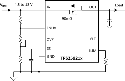
4 应用电路原理图

front_page_circuit_slvsce1.gif

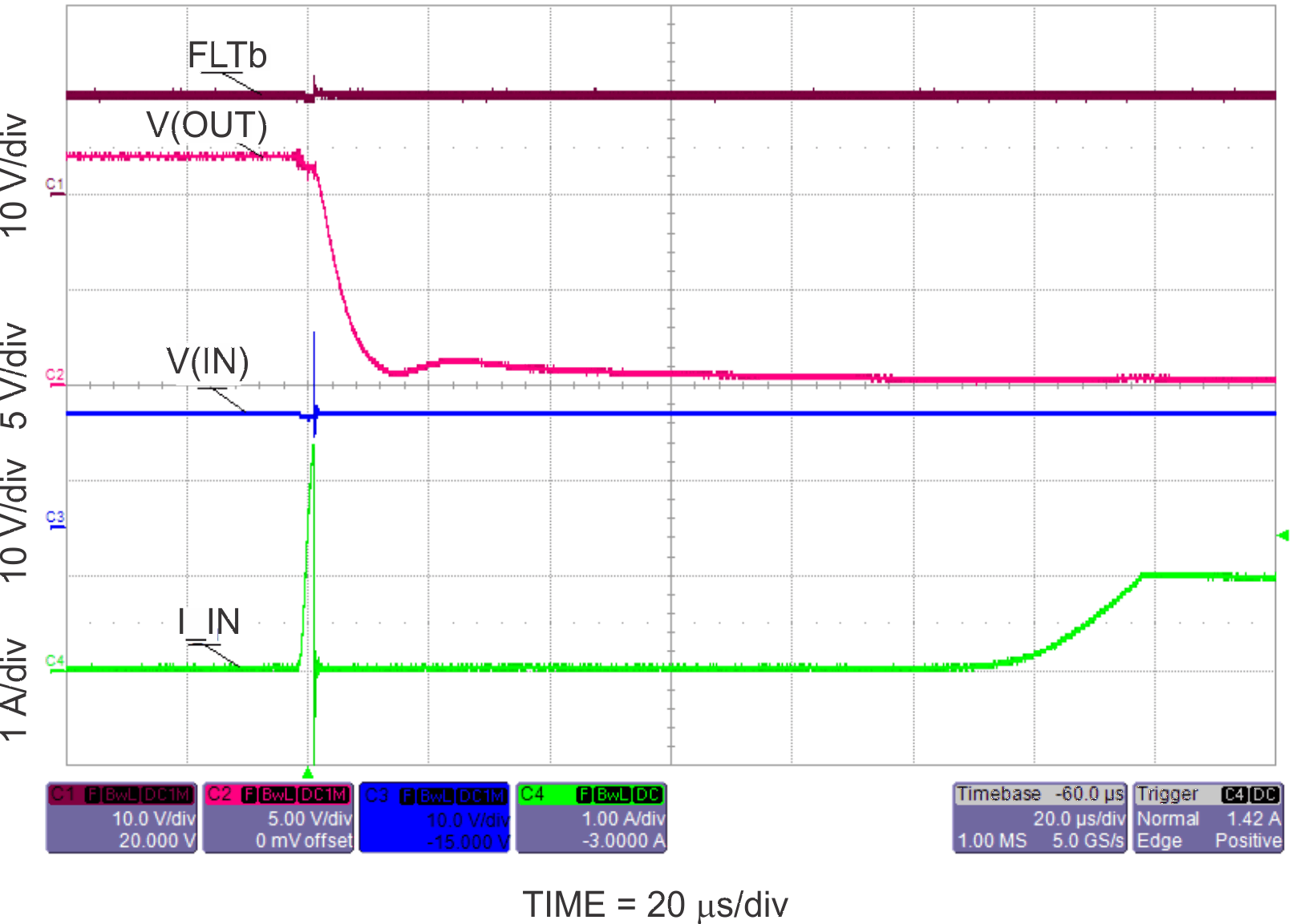
12V 短路响应

fp_Scope_SLVSCE1.gif