ZHCS749B January 2012 – January 2015 DS100DF410
PRODUCTION DATA.
- 1 特性
- 2 应用
- 3 说明
- 4 修订历史记录
- 5 Pin Configuration and Functions
- 6 Specifications
-
7 Detailed Description
- 7.1 Overview
- 7.2 Functional Block Diagram
- 7.3
Feature Description
- 7.3.1 Device Data Path Operation
- 7.3.2 Signal Detect
- 7.3.3 CTLE
- 7.3.4 DFE
- 7.3.5 Clock and Data Recovery
- 7.3.6 Output Driver
- 7.3.7 CTLE Boost Setting
- 7.3.8 DFE Tap Weight and Polarity Setting
- 7.3.9 Driver Output Voltage
- 7.3.10 Driver Output De-Emphasis
- 7.3.11 Driver Output Rise/Fall Time
- 7.3.12 Ref_mode 0 Mode (Reference Clock Not Required)
- 7.3.13 Ref_mode 3 Mode (Reference Clock Required)
- 7.3.14 False Lock Detector Setting
- 7.3.15 Reference Clock In
- 7.3.16 Reference Clock Out
- 7.3.17 Daisy Chain of REFCLK_OUT to REFCLK_IN
- 7.3.18 INT
- 7.3.19 LOCK_3, LOCK_2, LOCK_1, and LOCK_0
- 7.4 Device Functional Modes
- 7.5
Programming
- 7.5.1 SMBus Strap Observation
- 7.5.2 Device Revision and Device ID
- 7.5.3 Control/Shared Register Reset
- 7.5.4 Interrupt Channel Flag Bits
- 7.5.5 SMBus Master Mode Control Bits
- 7.5.6 Resetting Individual Channels of the Retimer
- 7.5.7 Interrupt Status
- 7.5.8 Overriding the CTLE Boost Setting
- 7.5.9 Overriding the VCO CAP DAC Values
- 7.5.10 Overriding the Output Multiplexer
- 7.5.11 Overriding the VCO Divider Selection
- 7.5.12 Using the PRBS Generator
- 7.5.13 Using the Internal Eye Opening Monitor
- 7.5.14 Overriding the DFE Tap Weights and Polarities
- 7.5.15 Enabling Slow Rise/Fall Time on the Output Driver
- 7.5.16 Inverting the Output Polarity
- 7.5.17 Overriding the Figure of Merit for Adaptation
- 7.5.18 Setting the Rate and Subrate for Lock Acquisition
- 7.5.19 Setting the Adaptation/Lock Mode
- 7.5.20 Initiating Adaptation
- 7.5.21 Setting the Reference Enable Mode
- 7.5.22 Overriding the CTLE Settings Used for CTLE Adaptation
- 7.5.23 Setting the Output Differential Voltage
- 7.5.24 Setting the Output De-emphasis Setting
- 7.6 Register Maps
- 8 Application and Implementation
- 9 Power Supply Recommendations
- 10Layout
- 11器件和文档支持
- 12机械封装和可订购信息
1 特性
- 每个通道独立锁定至 10.3125Gbps
- 锁定操作(通常不到 15ms)
- 低延迟(约 300ps)
- 具有自适应均衡功能,可在 5GHz 频率下提供最高 34dB 的升压
- 可调节的发送 VOD:600 至 1300mVp-p
- 可调节发送去加重功能:最高达 -12dB
- 典型功耗 (EQ + DFE + CDR + DE):每通道 180mW
- 可编程的输出极性反转
- 输入信号检测,CDR 锁定检测/指示器
- 片上眼图监视器 (EOM),伪随机二进制序列 (PRBS) 发生器
- 2.5V±5% 单电源
- 系统管理总线 (SMbus)/EEPROM 配置模式
- 工作温度范围 -40°C 至 85°C
- 48 引脚、7mm x 7mm 超薄四方扁平无引线 (WQFN) 封装
- 可轻松在中继器与重定时器之间进行引脚兼容升级
- DS100RT410 (EQ + CDR + DE):10.3125Gbps
- DS100DF410 (EQ + DFE + CDR + DE):10.3125Gbps
- DS110RT410 (EQ + CDR + DE):8.5–11.3Gbps
- DS110DF410 (EQ + DFE + CDR + DE):8.5–11.3Gbps
- DS125RT410 (EQ + CDR + DE):9.8–12.5Gbps
- DS125DF410 (EQ + DFE + CDR + DE):9.8–12.5Gbps
- DS100BR410 (EQ + DE):最高为 10.3125Gbps
2 应用
- 前端口 SFF 8431 (SFP+) 光学铜缆和直连铜缆
- 背板长度延长,数据重定时器
- 以太网:10GbE、1GbE
如需其他数据传输速率和数据传输协议,可使用重定时器系列的其他引脚兼容器件。
3 说明
DS100DF410 是一款具有集成信号调节功能的四通道重定时器。 每条通道均可独立锁定至 10.3125Gbps 数据传输速率,从而支持 10GbE。 该器件包括完全自适应的连续时间线性均衡器 (CTLE)、时钟和数据恢复 (CDR) 电路以及发送去加重 (DE) 驱动器。 DS100DF410 还包括自校准 5 抽头判决反馈均衡器 (DFE),可在较长的、有损且存在串扰的高速串行链路中传输数据,比特误差率 (BER) < 1×10-15。
可编程设置既可以通过 SMBus (I2C) 接口轻松应用,也可以通过外部 EEPROM 进行加载。 凭借片上眼图监视器和 PRBS 发生器,可以在系统调通或现场调试过程中实时测量高速串行数据。 DS100DF410 采用直通引脚和单电源,因此易于使用。
器件信息(1)
| 器件型号 | 封装 | 封装尺寸(标称值) |
|---|---|---|
| DS100DF410SQ | WQFN (48) | 7.00mm x 7.00mm |
- 要了解所有可用封装,请见数据表末尾的可订购产品附录。
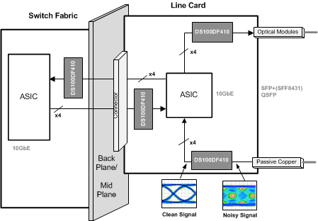
典型应用图

4 修订历史记录
Changes from A Revision (February 2013) to B Revision
- Changed ESD 额定值表,特性描述部分,器件功能模式,应用和实施部分,电源相关建议部分,布局部分,器件和文档支持部分以及机械、封装和可订购信息部分Go