ZHCSCQ8D August 2014 – September 2015 LM3644
PRODUCTION DATA.
- 1 特性
- 2 应用
- 3 说明
- 4 修订历史记录
- 5 Device Comparison Table
- 6 Pin Configuration and Functions
- 7 Specifications
-
8 Detailed Description
- 8.1 Overview
- 8.2 Functional Block Diagram
- 8.3 Feature Description
- 8.4 Device Functioning Modes
- 8.5 Programming
- 8.6
Register Descriptions
- 8.6.1 Enable Register (0x01)
- 8.6.2 IVFM Register (0x02)
- 8.6.3 LED1 Flash Brightness Register (0x03)
- 8.6.4 LED2 Flash Brightness Register (0x04)
- 8.6.5 LED1 Torch Brightness Register (0x05)
- 8.6.6 LED2 Torch Brightness Register (0x06)
- 8.6.7 Boost Configuration Register (0x07)
- 8.6.8 Timing Configuration Register (0x08)
- 8.6.9 TEMP Register (0x09)
- 8.6.10 Flags1 Register (0x0A)
- 8.6.11 Flags2 Register (0x0B)
- 8.6.12 Device ID Register (0x0C)
- 8.6.13 Last Flash Register (0x0D)
- 9 Applications and Implementation
- 10Power Supply Recommendations
- 11Layout
- 12器件和文档支持
- 13机械、封装和可订购信息
1 特性
- 两个可独立编程的 1.5A LED 电流源
- 准确的可编程 LED 电流范围为 1.4mA 到 1.5A
- 手电筒电流最高可达 360mA (LM3644TT)
- 闪光灯超时值最长可达 1.6 秒 (LM3644TT)
- 优化了低电池电量条件下的闪存 LED 电流(输入电压闪存监控器 (IVFM))
- 手电筒模式(100mA 时)和闪存模式(1A 至 1.5A 时)的效率超过 85%
- 支持阴极接地 LED 操作,改进了热管理
- 小型解决方案尺寸:< 16mm2
- 硬件选通使能 (STROBE)
- 射频功率放大器脉冲事件的同步输入 (TX)
- 硬件火炬使能 (TORCH/TEMP)
- 远程 NTC 监控 (TORCH/TEMP)
- 400kHz I2C 兼容接口
- LM3644(I2C 地址 = 0x63)
2 应用
可拍照手机白色 LED 闪光灯
3 说明
LM3644 是一款双 LED 闪存驱动器,能够以较小的解决方案尺寸提供高度可调节性。LM3644 采用 2MHz 或 4MHz 固定频率同步升压转换器为 1.5A 恒流 LED 源供电。 两个 128 级电流源可灵活调整 LED1 与 LED2 之间的电流比,。自适应调节方法可确保电流源保持可调节状态,并且最大限度地提升效率。
LM3643 LM3644 的功能由兼容 I2C 的接口控制。这些 功能 包括:硬件闪光灯和硬件手电筒引脚(STROBE 和 TORCH/TEMP)、TX 中断和负温度系数 (NTC) 热敏电阻监视器。器件在每个输出引脚均提供了可独立编程的电流,以便在闪存模式或录像(手电筒)模式条件下驱动 LED。
该器件的开关频率选项为 2MHz 或 4MHz,具备过压保护 (OVP) 和可调节限流功能,因此可采用微型超薄电感和 10μF 陶瓷电容。该器件的工作环境温度范围为 -40°C 至 +85°C。
器件信息(1)
| 器件型号 | 封装 | 封装尺寸(最大值) |
|---|---|---|
| LM3644 | 芯片级球状引脚栅格阵列 (DSBGA) (12) | 1.69mm x 1.31mm |
- 要了解所有可用封装,请见数据表末尾的可订购产品附录。
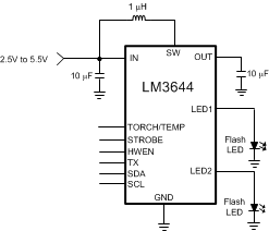
简化电路原理图
