ZHCSDR8 May 2015 TPS544B25 , TPS544C25
PRODUCTION DATA.
- 1 特性
- 2 应用范围
- 3 说明
- 4 修订历史记录
- 5 Device Comparison Table
- 6 Pin Configuration and Functions
- 7 Specifications
-
8 Detailed Description
- 8.1 Overview
- 8.2 Functional Block Diagram
- 8.3
Feature Description
- 8.3.1 Linear Regulators BP3 and BP6
- 8.3.2 Input Undervoltage Lockout (UVLO)
- 8.3.3 Turn-On and Turn-Off Delay and Sequencing
- 8.3.4 Voltage Reference
- 8.3.5 Differential Remote Sense
- 8.3.6 Set Output Voltage and Adapative Voltage Scaling (AVS)
- 8.3.7 Reset VOUT
- 8.3.8 Switching Frequency and Synchronization
- 8.3.9 Soft-Start and TON_RISE Command
- 8.3.10 Pre-Biased Output Start-Up
- 8.3.11 Soft-Stop and TOFF_FALL Command
- 8.3.12 Current Monitoring and Low-Side MOSFET Overcurrent Protection
- 8.3.13 High-Side MOSFET Short-Circuit Protection
- 8.3.14 Over-Temperature Protection
- 8.3.15 Output Overvoltage and Undervoltage Protection
- 8.3.16 TON_MAX Fault
- 8.3.17 Power Good (PGOOD) Indicator
- 8.3.18 Fault Protection Responses
- 8.3.19 Switching Node
- 8.3.20 PMBus General Description
- 8.3.21 PMBus Address
- 8.3.22 PMBus Connections
- 8.3.23 Auto ARA (Alert Response Address) Response
- 8.4 Device Functional Modes
- 8.5 Supported PMBus Commands
- 8.6
Register Maps
- 8.6.1 OPERATION (01h)
- 8.6.2 ON_OFF_CONFIG (02h)
- 8.6.3 CLEAR_FAULTS (03h)
- 8.6.4 WRITE_PROTECT (10h)
- 8.6.5 STORE_DEFAULT_ALL (11h)
- 8.6.6 RESTORE_DEFAULT_ALL (12h)
- 8.6.7 CAPABILITY (19h)
- 8.6.8 SMBALERT_MASK (1Bh)
- 8.6.9 VOUT_MODE (20h)
- 8.6.10 VOUT_COMMAND (21h)
- 8.6.11 VOUT_MAX (24h)
- 8.6.12 VOUT_TRANSITION_RATE (27h)
- 8.6.13 VOUT_SCALE_LOOP (29h)
- 8.6.14 VIN_ON (35h)
- 8.6.15 VIN_OFF (36h)
- 8.6.16 IOUT_CAL_OFFSET (39h)
- 8.6.17 VOUT_OV_FAULT_LIMIT (40h)
- 8.6.18 VOUT_OV_FAULT_RESPONSE (41h)
- 8.6.19 VOUT_OV_WARN_LIMIT (42h)
- 8.6.20 VOUT_UV_WARN_LIMIT (43h)
- 8.6.21 VOUT_UV_FAULT_LIMIT (44h)
- 8.6.22 VOUT_UV_FAULT_RESPONSE (45h)
- 8.6.23 IOUT_OC_FAULT_LIMIT (46h)
- 8.6.24 IOUT_OC_FAULT_RESPONSE (47h)
- 8.6.25 IOUT_OC_WARN_LIMIT (4Ah)
- 8.6.26 OT_FAULT_LIMIT (4Fh)
- 8.6.27 OT_FAULT_RESPONSE (50h)
- 8.6.28 OT_WARN_LIMIT (51h)
- 8.6.29 TON_DELAY (60h)
- 8.6.30 TON_RISE (61h)
- 8.6.31 TON_MAX_FAULT_LIMIT (62h)
- 8.6.32 TON_MAX_FAULT_RESPONSE (63h)
- 8.6.33 TOFF_DELAY (64h)
- 8.6.34 TOFF_FALL (65h)
- 8.6.35 STATUS_BYTE (78h)
- 8.6.36 STATUS_WORD (79h)
- 8.6.37 STATUS_VOUT (7Ah)
- 8.6.38 STATUS_IOUT (7Bh)
- 8.6.39 STATUS_INPUT (7Ch)
- 8.6.40 STATUS_TEMPERATURE (7Dh)
- 8.6.41 STATUS_CML (7Eh)
- 8.6.42 STATUS_MFR_SPECIFIC (80h)
- 8.6.43 READ_VOUT (8Bh)
- 8.6.44 READ_IOUT (8Ch)
- 8.6.45 READ_TEMPERATURE_2 (8Eh)
- 8.6.46 PMBUS_REVISION (98h)
- 8.6.47 MFR_VOUT_MIN (A4h)
- 8.6.48 IC_DEVICE_ID (ADh)
- 8.6.49 IC_DEVICE_REV (AEh)
- 8.6.50 MFR_SPECIFIC_00 (D0h)
- 8.6.51 OPTIONS (MFR_SPECIFIC_21) (E5h)
- 8.6.52 MISC_CONFIG_OPTIONS (MFR_SPECIFIC_32) (F0h)
-
9 Applications and Implementation
- 9.1 Application Information
- 9.2
Typical Applications
- 9.2.1 TPS544C25 4.5-V to 18-V Input, 0.95-V Output, 30-A Converter
- 9.2.2 Design Requirements
- 9.2.3
Design Procedure
- 9.2.3.1 Switching Frequency Selection
- 9.2.3.2 Inductor Selection
- 9.2.3.3 Output Capacitor Selection
- 9.2.3.4 Input Capacitor Selection
- 9.2.3.5 Bootstrap Capacitor Selection
- 9.2.3.6 BP6 and BP3
- 9.2.3.7 R-C Snubber and VIN Pin High-Frequency Bypass
- 9.2.3.8 Temperature Sensor
- 9.2.3.9 Key PMBus Parameter Selection
- 9.2.3.10 Output Voltage Setting and Frequency Compensation Selection
- 9.2.4 Application Curves
- 10Power Supply Recommendations
- 11Layout
- 12器件和文档支持
- 13机械、封装和可订购信息
1 特性
- 符合 PMBus 1.2 标准的转换器:20A 和 30A
- 输入电压范围:4.5V 至 18V
- 输出电压范围:0.5V 至 5.5V
- 5mm × 7mm LQFN 封装
- 单个散热焊盘
- 集成 5.5mΩ 和 2.0mΩ 堆叠 NexFET™功率级
- 用于通过 PMBus 进行自适应电压调节 (AVS) 和裕量调节的 500mV 至 1500mV 基准
- 电压不低于 600mV 时的精度为 0.5%
- 无损低侧金属氧化物半导体场效应晶体管 (MOSFET) 电流感测
- 具有输入前馈功能的电压模式控制
- 差分远程感应
- 单启动至预偏置输出
- 输出电压和输出电流报告
- 使用 2N3904 时的外部温度监视晶体管
- 可通过 PMBus 接口进行编程
- VOUT_COMMAND 和 AVS VOUT 转换率
- 具有热补偿功能的过流保护
- UVLO、软启动和软停止
- PGOOD、OV、UV、OT 电平
- 故障响应
- 接通和关闭延迟
- 热关断
- 引脚配置适用的开关频率:200kHz 至 1MHz
- 与外部时钟频率同步
- 封装兼容 20A、30A 转换器
2 应用范围
- 测试和测量仪器
- 以太网交换机、光交换机、路由器、基站
- 服务器
- 企业级存储固态硬盘 (SSD)
- 高密度电源解决方案
3 说明
TPS544x25 器件是采用 5mm × 7mm 封装且符合 PMBus 1.2 规范的非隔离式直流/直流转换器,具有集成的 FET,能够在高频下运行并输出 20A 或 30A 的电流。集成式 NexFET™功率级和经优化的驱动器提供的高频、低损耗开关支持密度极高的电源解决方案。PMBus 接口通过 VOUT_COMMAND 支持 AVS 功能,同时支持灵活的转换器配置以及关键参数(包括输出电压、电流和可选的外部温度)监控功能。对故障状况的响应可设置为重新启动、锁存或忽略,具体取决于系统要求。
器件信息
| 器件名称 | 封装 | 封装尺寸 |
|---|---|---|
| TPS544B25RVFT | LQFN (40) | 5.00mm x 7.00mm |
| TPS544C25RVFT | LQFN (40) | 5.00mm x 7.00mm |
.
.
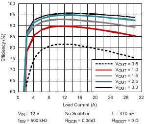
效率

4 修订历史记录
| 日期 | 修订版本 | 注意 |
|---|---|---|
| 2015 年 5 月 | * | 初始发行版。 |