ZHCSEO1C March   2012  – February 2016 TPS65177 , TPS65177A

PRODUCTION DATA.  

  1. 特性
  2. 应用
  3. 说明
  4. 修订历史记录
  5. Pin Configuration and Functions
  6. Specifications
    1. 6.1 Absolute Maximum Ratings
    2. 6.2 ESD Ratings
    3. 6.3 Recommended Operating Conditions
    4. 6.4 Thermal Information
    5. 6.5 Electrical Characteristics
    6. 6.6 I2C Interface Timing Characteristics
    7. 6.7 I2C Timing Diagram
    8. 6.8 Typical Characteristics
  7. Detailed Description
    1. 7.1 Overview
    2. 7.2 Functional Block Diagram
    3. 7.3 Feature Description
      1. 7.3.1 Power-Up
        1. 7.3.1.1 TPS65177
        2. 7.3.1.2 TPS65177A
      2. 7.3.2 Power-Down
      3. 7.3.3 Thermal Shutdown
      4. 7.3.4 Undervoltage Lockout
      5. 7.3.5 Short-Circuit and Overload Protection
        1. 7.3.5.1 Boost Converter (V(AVDD)):
        2. 7.3.5.2 Buck 1 Converter (V(IO)):
        3. 7.3.5.3 Buck 2 Converter (V(CORE)):
        4. 7.3.5.4 Buck 3 Converter (V(HAVDD)):
        5. 7.3.5.5 Positive Charge-Pump Controller (V(GH)):
        6. 7.3.5.6 Negative Charge-Pump Controller (V(GL)):
    4. 7.4 Device Functional Modes
      1. 7.4.1 Boost Converter (V(AVDD))
        1. 7.4.1.1 Soft-Start
        2. 7.4.1.2 Compensation
        3. 7.4.1.3 Setting the Output Voltage V(AVDD)
        4. 7.4.1.4 High Voltage Stress Mode (HVS)
        5. 7.4.1.5 Programmable Current Limit
        6. 7.4.1.6 Design Procedure
        7. 7.4.1.7 Inductor Selection
        8. 7.4.1.8 Rectifier Diode Selection
          1. 7.4.1.8.1 Diode Type
          2. 7.4.1.8.2 Forward Voltage
          3. 7.4.1.8.3 Reverse Voltage
          4. 7.4.1.8.4 Thermal Characteristics
        9. 7.4.1.9 Output Capacitor Selection
      2. 7.4.2 Buck 1 Converter (V(IO))
        1. 7.4.2.1 Soft-Start
        2. 7.4.2.2 Setting the Output Voltage V(IO)
        3. 7.4.2.3 Design Procedure
        4. 7.4.2.4 Inductor Selection
        5. 7.4.2.5 Rectifier Diode Selection
          1. 7.4.2.5.1 Diode Type
          2. 7.4.2.5.2 Forward Voltage
          3. 7.4.2.5.3 Reverse Voltage
          4. 7.4.2.5.4 Forward Current
          5. 7.4.2.5.5 Thermal Characteristics
        6. 7.4.2.6 Output Capacitor Selection
      3. 7.4.3 BUCK 2 CONVERTER (V(CORE))
        1. 7.4.3.1 Soft-Start
        2. 7.4.3.2 Setting the Output Voltage V(CORE)
        3. 7.4.3.3 Design Procedure
        4. 7.4.3.4 Inductor Selection
        5. 7.4.3.5 Output Capacitor Selection
      4. 7.4.4 Buck 3 Converter (V(HAVDD))
        1. 7.4.4.1 Soft-Start
        2. 7.4.4.2 Setting the Output Voltage V(HAVDD)
        3. 7.4.4.3 High Voltage Stress Mode (HVS)
        4. 7.4.4.4 Design Procedure
        5. 7.4.4.5 Inductor Selection
        6. 7.4.4.6 Output Capacitor Selection
      5. 7.4.5 Positive Charge Pump Controller (V(GH)) with Temperature Compensation
        1. 7.4.5.1 Soft-Start
        2. 7.4.5.2 Setting the Output Voltage V(GH)
        3. 7.4.5.3 Design Procedure
        4. 7.4.5.4 Output Capacitor Selection
      6. 7.4.6 Negative Charge Pump Controller (V(GL))
        1. 7.4.6.1 Soft-Start
        2. 7.4.6.2 Setting the Output Voltage V(GL)
        3. 7.4.6.3 Design Procedure
        4. 7.4.6.4 Output Capacitor Selection
    5. 7.5 Gate Pulse Modulation (V(GHM))
    6. 7.6 Programming
      1. 7.6.1  I2C Serial Interface Description
      2. 7.6.2  Memory Description
      3. 7.6.3  Read / Write Description
      4. 7.6.4  Write Operation
        1. 7.6.4.1 Write Single Byte to the DAC Register (DR):
        2. 7.6.4.2 Write Multiple Bytes to the DAC Register (DR):
        3. 7.6.4.3 Write All DAC Register (DR) Data to EEPROM (EE):
      5. 7.6.5  READ OPERATION
        1. 7.6.5.1 Read single data from DAC register (DR):
        2. 7.6.5.2 Read Multiple Data from DAC Register (DR):
        3. 7.6.5.3 Read Single Data to EEPROM (EE):
        4. 7.6.5.4 Read Multiple Data to EEPROM (EE):
      6. 7.6.6  Write Single Data to DAC:
      7. 7.6.7  Write Multiple Data to DAC (Auto Increment Address):
      8. 7.6.8  Write all DAC Data to EEPROM:
      9. 7.6.9  Read Single Data From DAC / EEPROM:
      10. 7.6.10 Read Multiple Data fFom DAC / EEPROM (Auto Increment Address):
    7. 7.7 Register Map
      1. 7.7.1 Registers and DAC Settings
        1. 7.7.1.1  Channel Register (with factory value) - 00h (00h)
        2. 7.7.1.2  Boost Output Voltage V(AVDD) Register (with factory value) - 01h (0Fh)
        3. 7.7.1.3  Boost HVS Offset Voltage Register (with factory value) - 02h (05h)
        4. 7.7.1.4  Boost Current Limit Negative Offset Current Register (with factory value) - 03h (00h)
        5. 7.7.1.5  Boost Soft-start Time Register (with factory value) - 04h (00h)
        6. 7.7.1.6  Buck 1 Output Voltage V(IO) Register (with factory value) - 05h (03h):
        7. 7.7.1.7  Buck 2 Output Voltage V(CORE) Register (with factory value) - 06h (02h)
        8. 7.7.1.8  Buck 3 Output Voltage V(HAVDD) Register (with factory value) - 07h (1Bh)
        9. 7.7.1.9  Pos. Charge Pump Low Output Voltage V(GH_L) Register (with factory value) - 08h (08h):
        10. 7.7.1.10 Positive Charge Pump Low Output Voltage V(GH_L) to V(GH_H) Positive Offset Voltage V(GH_OFS) Register (with factory value) - 09h (04h):
        11. 7.7.1.11 Gate Pulse Modulation Limit Voltage Register (with factory value) - 0Ah (00h)
        12. 7.7.1.12 Negative Charge Pump Output Voltage V(GL) Register (with factory value) - 0Bh (04h)
        13. 7.7.1.13 Buck 3 HVS Offset Voltage Register (with factory value) - 0Ch (00h):
        14. 7.7.1.14 Memory Write Remain Time Register (with factory value) - FEh (0Fh):
  8. Application and Implementation
    1. 8.1 Application Information
    2. 8.2 Typical Applications
      1. 8.2.1 Design Requirements
      2. 8.2.2 Detailed Design Procedure
      3. 8.2.3 Application Curves
    3. 8.3 System Examples
  9. Power Supply Recommendations
  10. 10Layout
    1. 10.1 Layout Guideline
    2. 10.2 Layout Example
  11. 11器件和文档支持
    1. 11.1 相关链接
    2. 11.2 Third-Party Products Disclaimer
    3. 11.3 社区资源
    4. 11.4 商标
    5. 11.5 静电放电警告
    6. 11.6 Glossary
  12. 12机械、封装和可订购信息

封装选项

机械数据 (封装 | 引脚)
散热焊盘机械数据 (封装 | 引脚)
订购信息

1 特性

  • 使能/禁用
    • TPS65177:AVI 掉电再上电
    • TPS65177A:VI 掉电再上电或 EN 引脚
  • 8.6V 到 14.7V 输入电压范围
  • 非同步升压转换器 (V(AVDD))
    • 集成隔离开关
    • 13.5V 到 19.8V 输出电压 (I2C)
    • 15V 默认输出电压
    • 4.25A 开关电流限制 (I2C)
    • 高压应力模式 (I2C)
  • 同步降压转换器 (V(HAVDD))
    • 4.8V 到 11.1V 输出电压 (I2C)
    • 7.5V 默认输出电压
    • 1.7A 开关电流限制
    • 高压应力模式 (I2C)
  • 非同步降压转换器 (V(IO))
    • 2.2V 到 3.7V 输出电压 (I2C)
    • 2.5V 默认输出电压
    • 3A 开关电流限制
  • 同步降压转换器 (V(CORE))
    • 0.8V 到 3.3V 输出电压 (I2C)
    • 1V 默认输出电压
    • 2.5A 开关电流限制
  • 正电荷泵控制器 (V(GH))
    • 20V 到 40V 输出电压 (I2C)
    • 28V 默认输出电压
    • 温度补偿偏移:0V 到 15V (I2C)
    • 4V 默认偏移(28V 到 32V)
  • 负电荷泵控制器 (V(GL))
    • –14.5V 到 –5.5V 输出电压 (I2C)
    • –7.9V 默认输出电压
  • 栅极脉冲调制 (GPM)
    • 低至 0V、5V、10V 或 15V (I2C)
    • 0V 默认放电电压
  • V(GH) 的温度补偿
  • 热关断
  • I2C 兼容接口
  • EEPROM 存储器
  • 6mm × 6mm × 1mm 40 引脚超薄四方扁平无引线 (VQFN) 封装

2 应用

  • GIP (Gate-in-Panel) 液晶显示屏 (LED) 电视 (TV)
  • 非 GIP LCD TV

3 说明

TPS65177/A 可提供 GIP (Gate-in-Panel) 或非 GIP 薄膜晶体管 (TFT)-LCD 面板所需的所有电源轨。所有输出电压均可通过 I2C 编程设定。

V(IO) 和 V(CORE) 用于 T-CON,V(AVDD) 和 V(HAVDD) 用于拉电流驱动器和伽马缓冲器,V(GH) 和 V(GL) 用于栅极驱动器或电平转换器。为了与非 GIP 技术搭配使用,实现了栅极脉冲调制 (GPM);为了与 GIP 技术搭配使用,可对 V(GH) 轨进行温度补偿。此外,还针对 V(AVDD) 和 V(HAVDD) 提供了一种高压应力模式 (HVS),并且实现了一个集成式 V(AVDD) 隔离开关。V(CORE)、V(HAVDD)、V(GH)、V(GL)、GPM 和 V(GH) 温度补偿可通过 I2C 编程来使能与禁用。

单一 BOM(物料清单)可涵盖多种面板类型和尺寸,这些面板所需的输出电压可以在生产时进行编程并存储于非易失性集成存储器中。

器件信息(1)

器件型号 封装 封装尺寸(标称值)
TPS65177 VQFN(40 引脚) 6.00mm x 6.00mm
TPS65177A VQFN(40 引脚) 6.00mm x 6.00mm
  1. 要了解所有可用封装,请见数据表末尾的可订购产品附录。

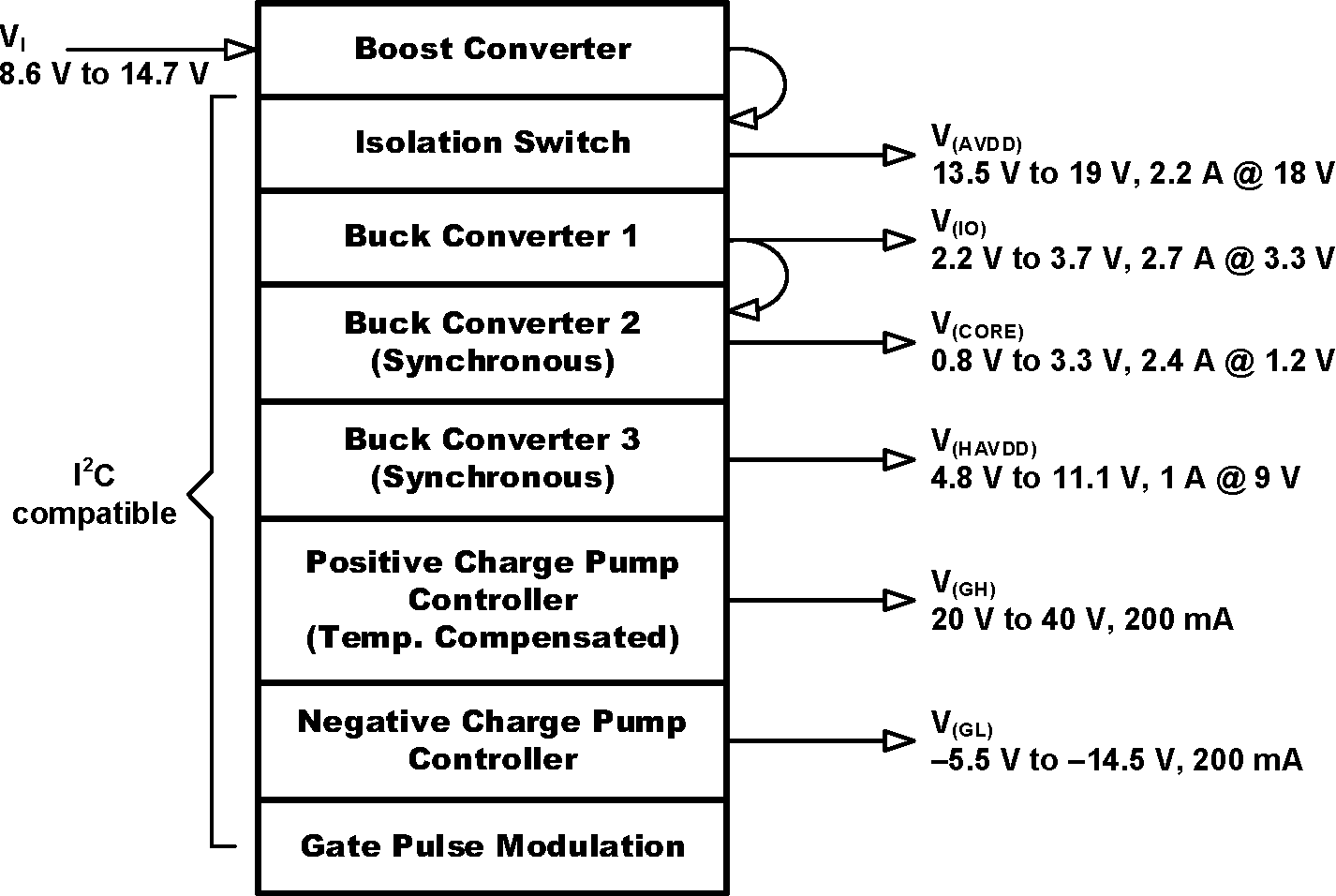
方框图

TPS65177 TPS65177A Overview.gif

4 修订历史记录

Changes from B Revision (January 2016) to C Revision

  • Added TPS65177A 器件并已更改 特性 描述,多张图片的颜色 Go

Changes from A Revision (July 2012) to B Revision

  • 已添加 ESD 额定值表,特性 描述部分,器件功能模式部分,应用和实施部分,电源相关建议部分,布局部分,器件和文档支持部分以及机械、封装和可订购信息部分。Go
  • Added text to the Power-Up section, " If the EN pin is not connected to VIN..."Go

Changes from * Revision (March 2012) to A Revision

  • Changed PR equationGo
  • Deleted Inverting Doubler: VGL_max equationGo
  • Deleted Inverting Doubler: VGL_max equationGo
  • Deleted Inverting Doubler: PDIS equationGo
  • Deleted Inverting Doubler: PDIS equationGo
  • Changed PR equationGo
  • Changed Figure 46, Figure 47, Go
  • Changed Figure 48Go