ZHCSF62D March 2016 – June 2017 TPS65320C-Q1
PRODUCTION DATA.
- 1 特性
- 2 应用
- 3 说明
- 4 修订历史记录
- 5 Pin Configuration and Functions
- 6 Specifications
-
7 Detailed Description
- 7.1 Overview
- 7.2 Functional Block Diagram
- 7.3
Feature Description
- 7.3.1
Buck Regulator
- 7.3.1.1 Fixed-Frequency PWM Control
- 7.3.1.2 Slope Compensation Output
- 7.3.1.3 Pulse-Skip Eco-mode™ Control Scheme
- 7.3.1.4 Dropout Mode Operation and Bootstrap Voltage (BOOT)
- 7.3.1.5 Error Amplifier
- 7.3.1.6 Voltage Reference
- 7.3.1.7 Adjusting the Output Voltage
- 7.3.1.8 Soft-Start Pin (SS)
- 7.3.1.9 Overload-Recovery Circuit
- 7.3.1.10 Constant Switching Frequency and Timing Resistor (RT/CLK Pin)
- 7.3.1.11 Overcurrent Protection and Frequency Shift
- 7.3.1.12 Selecting the Switching Frequency
- 7.3.1.13 How to Interface to RT/CLK Pin
- 7.3.1.14 Overvoltage Transient Protection
- 7.3.1.15 Small-Signal Model for Loop Response
- 7.3.1.16 Simple Small-Signal Model for Peak-Current Mode Control
- 7.3.1.17 Small-Signal Model for Frequency Compensation
- 7.3.2 LDO Regulator
- 7.3.3 Thermal Shutdown
- 7.3.4 Power-Good Output, nRST
- 7.3.5 Enable and Undervoltage Lockout
- 7.3.1
Buck Regulator
- 7.4 Device Functional Modes
-
8 Application and Implementation
- 8.1 Application Information
- 8.2
Typical Application
- 8.2.1
2-MHzSwitching Frequency, 9-V to 16-V Input, 5-V Output Buck Regulator, 3.3-V Output LDO Regulator
- 8.2.1.1 Design Requirements
- 8.2.1.2
Detailed Design Procedure
- 8.2.1.2.1 Switching Frequency Selection for the Buck Regulator
- 8.2.1.2.2 Output Inductor Selection for the Buck Regulator
- 8.2.1.2.3 Output Capacitor Selection for the Buck Regulator
- 8.2.1.2.4 Catch Diode Selection for the Buck Regulator
- 8.2.1.2.5 Input Capacitor Selection for the Buck Regulator
- 8.2.1.2.6 Soft-Start Capacitor Selection for the Buck Regulator
- 8.2.1.2.7 Bootstrap Capacitor Selection for the Buck Regulator
- 8.2.1.2.8 Output Voltage and Feedback Resistor Selection for the Buck Regulator
- 8.2.1.2.9 Frequency Compensation Selection for the Buck Regulator
- 8.2.1.2.10 LDO Regulator
- 8.2.1.2.11 Power Dissipation
- 8.2.1.2.12 Power Dissipation Losses of the LDO Regulator
- 8.2.1.2.13 Total Device Power Dissipation Losses and Junction Temperature
- 8.2.1.3 Application Curves
- 8.2.1
2-MHzSwitching Frequency, 9-V to 16-V Input, 5-V Output Buck Regulator, 3.3-V Output LDO Regulator
- 9 Power Supply Recommendations
- 10Layout
- 11器件和文档支持
- 12机械、封装和可订购信息
1 特性
- 符合汽车应用 要求
- 具有符合 AEC-Q100 的下列结果:
- 器件温度 1 级:-40°C 至 +125°C 的环境运行温度范围
- 器件 HBM ESD 分类等级 2
- 器件组件充电模式 (CDM) ESD 分类等级 C4B
- 一个高输入电压降压 DC/DC 转换器
- 输入范围:3.6V 到 36V
- 250mΩ 高侧 MOSFET
- 最大负载电流为 3.2A,输出的可调节范围为 1.1V 到 20V
- 可调开关频率范围为 100kHz 至 2.5MHz
- 同步至外部时钟
- 利用脉冲跳跃 Eco-mode™ 控制方案在轻负载条件下实现了高效率
- 140µA 最大静态工作电流
- 一个低压降 (LDO) 稳压器
- 为两个稳压器提供过流保护
- 过热保护
- 14 引脚带散热片的薄型小尺寸 (HTSSOP) 封装,此封装具有 PowerPAD™集成电路封装
2 应用
- 汽车信息娱乐和仪表板
- 高级驾驶员辅助系统 (ADAS)
- 汽车远程信息处理,紧急呼叫
3 说明
TPS65320C-Q1 器件结合了一个高输入电压 DC-DC 降压转换器(也称降压稳压器,其开关模式频率可调节范围为 100kHz 到 2.5MHz)和一个高输入电压 280mA 低压降 (LDO) 稳压器。降压稳压器的输入范围为 3.6V 到 36V,LDO 稳压器的输入范围为 3V 到
20 V。该降压稳压器集成一个高侧 MOSFET。LDO 稳压器 具有 一个空载条件下典型值为 45μA 的低输入电流,同时集成一个 MOSFET,带有低电平有效推挽复位输出引脚。 处于工作状态时,LDO 稳压器的输入电源自动拉取降压稳压器的输出。 TPS65320C-Q1 的低压跟踪特性可在冷启动条件下跟踪输入电源。
降压稳压器根据系统需求提供灵活设计。外部回路补偿电路可优化转换器响应,从而达到合适的工作条件。低纹波脉冲跳跃模式将无负载输入电源电流降至不超过 140μA。
此器件内置保护 特性, 例如软启动、限流和热感应并在功耗超量的情况下关断。另外,该器件具有内部欠压锁定 (UVLO) 功能,可在电源电压过低的情况下关闭。
器件信息(1)
| 器件型号 | 封装 | 封装尺寸(标称值) |
|---|---|---|
| TPS65320C-Q1 | HTSSOP (14) | 5.00mm x 4.40mm |
- 如需了解所有可用封装,请参阅数据表末尾的可订购产品附录。
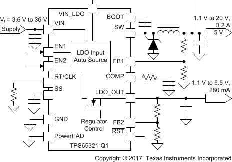
典型应用电路原理图

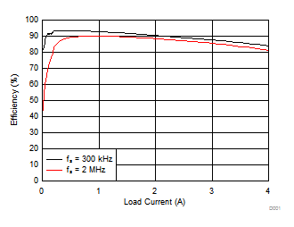
降压效率与输出电流间的关系
