DLPA130A December 2021 – February 2022 DLP780NE , DLP780TE , DLP781NE , DLP781TE , DLP800RE , DLP801XE
1 Application Brief
Introduction
Light emitting diodes (LEDs) offer significant advantages over HID lamp, laser pumped phosphor (LaPh) and laser light sources when used in TI DLP® Products projectors and provide significant competitive advantages when compared to 3LCD projectors. While LEDs do not currently offer the ability to achieve the high (6000+) lumens that is achievable with the other light sources, they do create a significantly better and cost-effective image experience with excellent color saturation and color balance, high speed color switching with no moving parts, no speckle, long lifetimes and durability. This document describes the LED advantages, system options and illumination optical design of DLP projectors using high-powered, projection LEDs.
Advantages of LED Projection Light Sources for DLP Projection
Over the past ten years, LEDs have continuously increased their luminous output capability and are now at or approaching the lumen levels equivalent to HID lamp and LaPh projectors for the mainstream projector market. Single chip DLP LED projectors are capable of producing 3000-5000 lumens depending on the DMD (Digital Micromirror Device) and LED illumination design.
There are several significant advantages of a projector system with LED illumination. LED projectors display beautiful and vibrant colors and can fully cover the Rec. 709 color gamut which considerably exceeds those of lamp and LaPh systems from other competing projection technologies.
Advantages of LED Projection
- Wide color gamut
- Long operational lifetime
- Instant on/off
- No speckle (unlike lasers, there is not need for de-speckling)
- Brightness boost from pulsed operation (advantage of single chip)
- No "spokes" or dark time due to high speed switching
- Brightness boost with color overlap of yellow or cyan or both (single chip)
- Year-on-year LED luminous output improvement
DLP projection technology takes full advantage of the unpolarized output of LED light sources since DLP technology does not require or depend on polarization to create bright or dark pixels. The full light emission of the LED can be utilized with DLP without the need for polarization recovery techniques.
High-Power Projection LED Vendors
ams OSRAM and Luminus Devices, Inc. are two popular LED vendors that produce high-powered LEDs for DLP projection. Their portfolios include projection devices with packages and LED emitters that are compatible in aspect ratio and etendue to popular DLP projection platforms. Each vendor continues to develop high-powered chips and LED boards that are optimized for high flux and thermal management.
LED Spectra and Color Gamut
There are several variations of high-powered LEDs that are used for projection. Blue and red are typical, while the green LED is most often a blue LED with a phosphor layer on the emitting surface. This type of green LED is referred to as a phosphor green or converted green (CG). These converted green LEDs have a broad spectral emission band and can achieve much higher luminous flux than a standard “true green” LED. True green LEDs with a typical narrow band LED spectrum are also available but seldom used for projection due to lower luminous output compared to the converted green LED.
Other LEDs are also available that when their spectra are added to R, G and B, enhance the luminous flux or color gamut of the projection system. There is also a shorter wavelength blue LED, which is used to send light onto the top surface of the converted green LED phosphor to create a 4-channel system. This deep blue LED is often referred to as a top-side-pump or blue-pump LED. The blue-pump LED can increase the flux output of the green LED by as much as 40%. The full boost of the converted green LED however cannot be fully realized if the red LED cannot supply enough red light to provide a good white color point. The 4-channel system can achieve around a 15% increase in light due to this top-side-pump blue LED addition. Some vendors are also supplying a longer wavelength red LED. Light from the longer wavelength red LED when added to the light from the standard red LED increases the total amount of red light available which then allows for more of the top-side-pump green light to be used to increase brightness. The longer wavelength red LED light also increases the color gamut of the projector and color volume. The spectra of a blue, converted-green, amber (red) and long wavelength red LEDs are shown in Figure 1-2.
The selection of LEDs or combinations of LEDs and LED sizes and output powers greatly depend on the application. As a general rule, the larger the LED emitter surface area the higher the projector lumens, up until the LED etendue exceeds that of the DMD and projector system.
LED Selection for DLP Projection
The selection of LED for the application begins with the assessment of projector system throughput or etendue. The DMD and projection system f/# sets this etendue value for the LED. The aspect ratio of the DMD selected for the projection application in conjunction with the optical illumination architecture determine an ideal aspect ratio for the LED. The ideal LED is one that matches both the etendue and the aspect ratio for the projection design. Due to the limited sizes and aspect ratios of commercially available LEDs, the designer needs to find the best matched set of LEDs for the application. The best matched set may even require the mixing of LEDs of different sizes and power output levels to achieve the desired result.
LED Sizing
The ideal size of the LED can be calculated using the projection system optical specifications of 1) DMD tilt angle, 2) DMD overfill, 3) DMD area, 4) DMD illumination f/#, and 5) LED collection angle. The LED is the ideal size if the etendue is matched along with the aspect ratio.
The aspect ratio match of the DMD and LED can be calculated by splitting the etendue into their respective width and height components. In the following equations, the common variables are defined in Table 1-1.
| Variable | Definition |
|---|---|
| dDMD_pixel_pitch | Pixel pitch of the DMD |
| wwidth_pixels | Number of pixels in the horizontal direction of the DMD array |
| hheight_pixels | Number of pixels in the vertical direction of the DMD array |
| Overfill | Fraction of the total illumination light that illuminates the DMD array |
| θcollection_angle | LED collimater half angle of collection |
| θwidth_axis_cone | half angle of the projected light cone in the horizontal direction |
| θheight_axis_cone | half angle of the projected light cone in the vertical direction |
| θtilt | DMD mirror tilt angle |
For a DMD device is illuminated from the side, the ideal LED size is given by Equation 2 for the width of the LED and Equation 3 for the height of the LED.
Where the factor a is a value greater or equal to 1.0 and is based on the specific optical design.
The illumination cone half angle is related to the f/# by Equation 5.
For a DMD device is illuminated from the bottom, the ideal LED size is given by Equation 6 for the width of the LED and Equation 7 for the height of the LED.
For a DMD device that is illuminated along the diagonal, the ideal LEDs size is given by Equation 8 for the width of the LED and Equation 9 for the height of the LED.
The coupling efficiency of the LED to the DMD can be calculated by comparing the ideal LED width and height to the actual LED width and height, as shown in Equation 10.
Example for the DLP800RE DMD
The following is an example of the calculation for ideal LED size and nearest LEDs available for the DLP800RE DMD.
The DLP800RE DMD has an aspect ratio of 16:10, a resolution of WUXGA and a diagonal of 0.8-inches.
| Optical Design Parameter | Value |
|---|---|
| d DMD_pixel_pitch (mm) | 0.009 |
| wwidth_pixels x hheight_pixels | 1920 x 1200 |
| Overfill | 85% |
| θwidth_axis_cone | 14.48° (f/2.0) |
| θheight_axis_cone | 14.48° (f/2.0) |
| θcollection_angle | 75° |
| Anamorphism | 1.13 |
| Illumination Orientation | diagonal |
The ideal LED size using the above DMD and optical system parameters and the diagonal illumination equations, Equation 8 and Equation 9, is 4.56 mm x 2.85 mm. The coupling efficiency with LED available in the market can be calculated using the above coupling efficiency formula.
| Width (mm) | Height (mm) | Coupling Efficiency | |
|---|---|---|---|
| OSRAM P2MQ | 3.2 | 2.6 | 100% |
| OSRAM P3MQ | 4.85 | 2.6 | 95.1% |
| Luminus PTM-130X | 4.78 | 2.7 | 95.5% |
A comparison of the above LEDs and the ideal LED can also be examined using a plot of the dimensions. Each of the LED dimension are plotted on the chart and are compared with the ideal LED. If the LED is completely contained within the dimensions of the ideal LED, then the coupling efficiency is 100%. Any LED with a larger size than the ideal LED for the projection system is not be efficiently collected. An area of the ideal LED that is not covered or matched by the selected LED is system capability that is available but not used by the selected LED. The OSRAM P2MQ is an example of this aspect, the LED is coupled by the projection system at 100% efficiency, but there is 56% more potential LED area to create light that can be coupled by the projection system and thus produce a brighter projector. The area outside the red dotted box but inside the solid black box is the unused LED area in Figure 1-5.
Cost, size and thermal control may also play a factor in the decision to use a given LED or another. In this case, for maximum lumens, the OSRAM P3MQ or Luminus PTM-130X are possible LEDs of choice. If a lower cost projector in a smaller form factor is valued, then an OSRAM P2MQ or similar LED may be the most appropriate.
The LED selection ultimately depends on product performance and cost targets. However, finding the best LED for the design starts with an assessment of etendue, aspect ratio and coupling efficiency. These LED coupling values can be used to develop a projector system lumen budget.
LED Collimator Optics
There are many forms of light collection optics for LEDs. The most common collimator for projection applications is a high collection angle two lens transmissive optical design. The two lens collimator is used in conjunction with a focusing or condenser optic to form an image the of LED either at the input surface of a light tunnel, or at the second lens surface of a fly’s eye array (FEA).
LED Emission vs. Angle and Target Collection Angle for Collimator
The collimator must be designed to efficiently collect light from the LED with a half cone angle in the range of ~ 70°-80° to ensure good fraction of the total light emitted by the LED is collected. LED emission can be assumed to be Lambertian with a cone angle of emission of ± 90°. The percentage of the total light emitted by the LED is approximated by Equation 11.
Figure 1-6 shows collection angle in the range of 70°-80° is between 88% and 97 % of the emitted light from the LED. Collecting more than 80° has diminishing returns in terms of optical performance and surface losses while collecting less than 70° collects too little of the LED emitted light and contributes too much to the loss of efficiency.
Collimator Design Example
The typical design of the collimator optic consists of small spherical glass element and a second larger glass or plastic aspherical element. The first collimator lens is very close to the LED and must take a significant amount of heat. Glass elements are used both for the high index of refraction and to avoid any softening or melting of plastic optics in close proximity to the high brightness LED. The second collimator may be glass or plastic and is typically aspheric to help with high angle ray error correction. An example of a typical collimator is shown below.
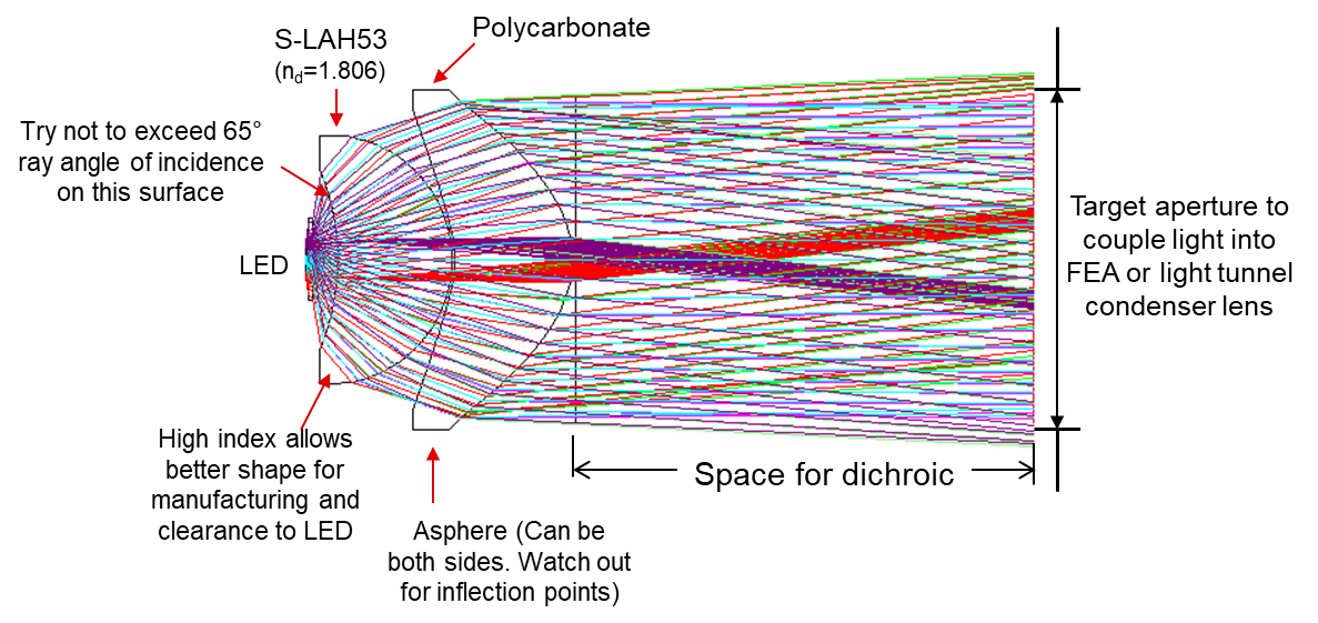 Figure 1-7 Example of Collimator Optical Design
and Key Design Considerations
Figure 1-7 Example of Collimator Optical Design
and Key Design ConsiderationsFor projection design, it is important to reduce the collimator size as much as possible. Smaller collimators result in reduced cost and a smaller optical layout. When the collimator optics are smaller, the lenses for each color channel can be located closer together which yields a smaller mechanical envelope for the entire LED illuminator. The diameter of the LED collimator is affected by the LED emitter diagonal dimension, the collection angle of LED emission, and the proximity of the first collimator lens to the LED emitter. Trade-offs between mechanical mounting, collimator to LED alignment, manufacturing cost, collection efficiency and optical quality need to be made to determine the best collimator design solution for the projection application.
There are no standard optical collimators for LEDs because they depend highly on the complete projector optical system requirements. Once an LED collimator is designed for a specific LED however, it is possible to reuse those designs for similar projector systems. Other methods such as 3 lens collimators have been used to improve the coupling efficiency and image quality for LED collimation. Usually, it is not necessary to use a 3rd lens element for the collimator as improvements are often marginal compared to the added size and cost of the collimator optics. Single lens LED collimator optics are used in some projection systems where manufacturing cost was a significant driver. Optical correction limits the single lens collimator to a collection angles under 60° where the light collection efficiency is low.
LED Illuminator Layout Options
The optical paths for each of the LED sources and LED collimators need to be combined into a single path for input to the illumination relay optics. There are several different arrangements, each with their specific attributes. A specific layout may be preferred based on the requirements, whether that be the most suitable for a given thermal design or to achieve smallest footprint or for maximum lumens.
Illuminator LED Combination Options and Layouts
For many projection applications, the red LED places a limit on the total color balanced lumen level of the projected image. The coupling efficiency between the light leaving the collimator lenses and the FEA or light tunnel is greatest when the separation between these planes is the smallest. If a particular layout has different distances between the collimator lens and the light tunnel or FEA for each color channel, it is recommended that the red LED be placed in the shortest optical path to the FEA or light tunnel to maximize the throughput of red light.
The top-side-pump (TSP) or RGBB LED arrangement adds a deep blue LED to illuminate the top side of the phosphor coated converted green LED. The TSP arrangement allows the phosphor to be excited from both sides simultaneously, raising the flux of the converted green LED by as much as 40%. All of this added green flux is not usable when the system is color balanced for typical projector white points due to the limited red LED output.
The addition of a long wavelength red LED (or red laser) to the TSP 4-channel LED illuminator allows more use of the TSP green light from the RGBB system. The added long wavelength red LED channel improves both brightness and color saturation of the red.
Examples of possible illuminator layouts are for RGB, RGBB, RGBB+long wavelength red and P3 chromaticity gamut arrangements are shown in Figure 1-8. The optical filters f1, f2, f3 and fg are dichroic filters.
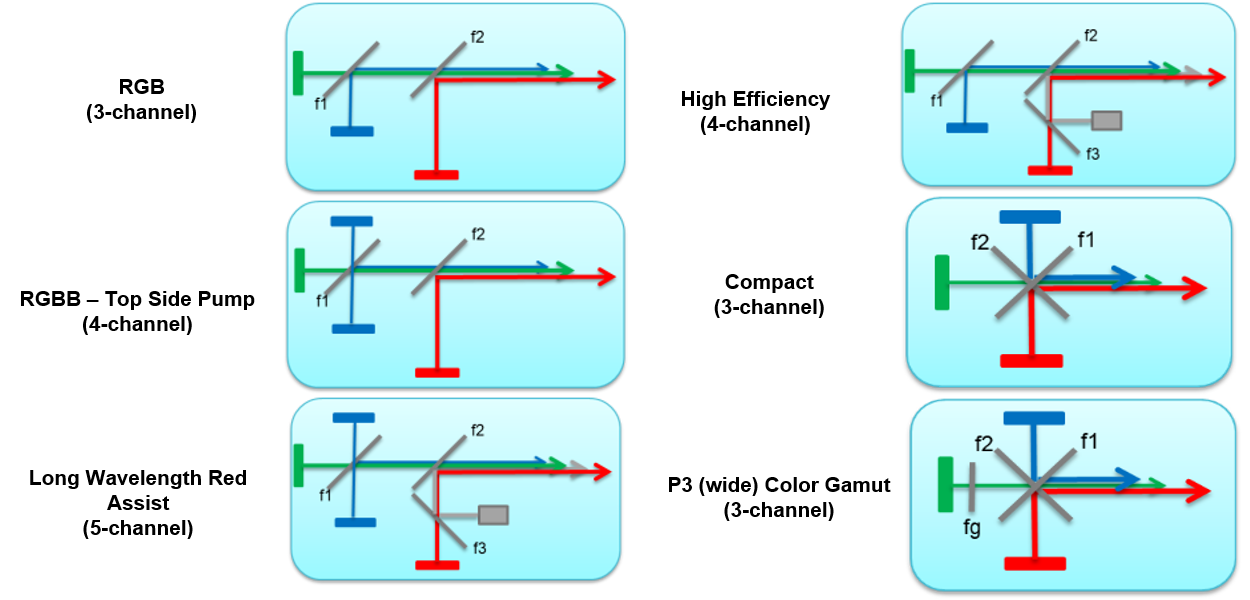 Figure 1-8 LED Illuminator Layout Options
Dichroic Filter Design
Dichroic filter plates are needed to combine LED light of the various colors into one path. In each case, the color is either transmitted or reflected. The designer has a choice as to where the filter cut off point is for each dichroic filter. These dichroic filter curves are designed around realistic 90%-10% slopes and 50%-point shift fabrication tolerances as well as desired color point and luminous flux. The goal is to combine all of these factors and performance targets together to produce an optimal filter design. The following charts are examples of dichroic filter curves for the LED illuminators and can be used as starting points for custom designs. The following dichroic combination filters are all at 45deg angle of incidence (AOI).
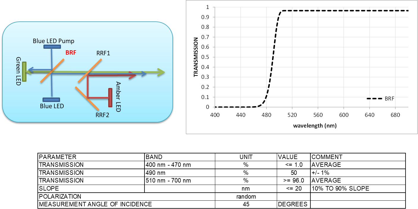 Figure 1-9 Blue/Green Dichroic Filter Design
(Blue Reflect Filter, BRF)
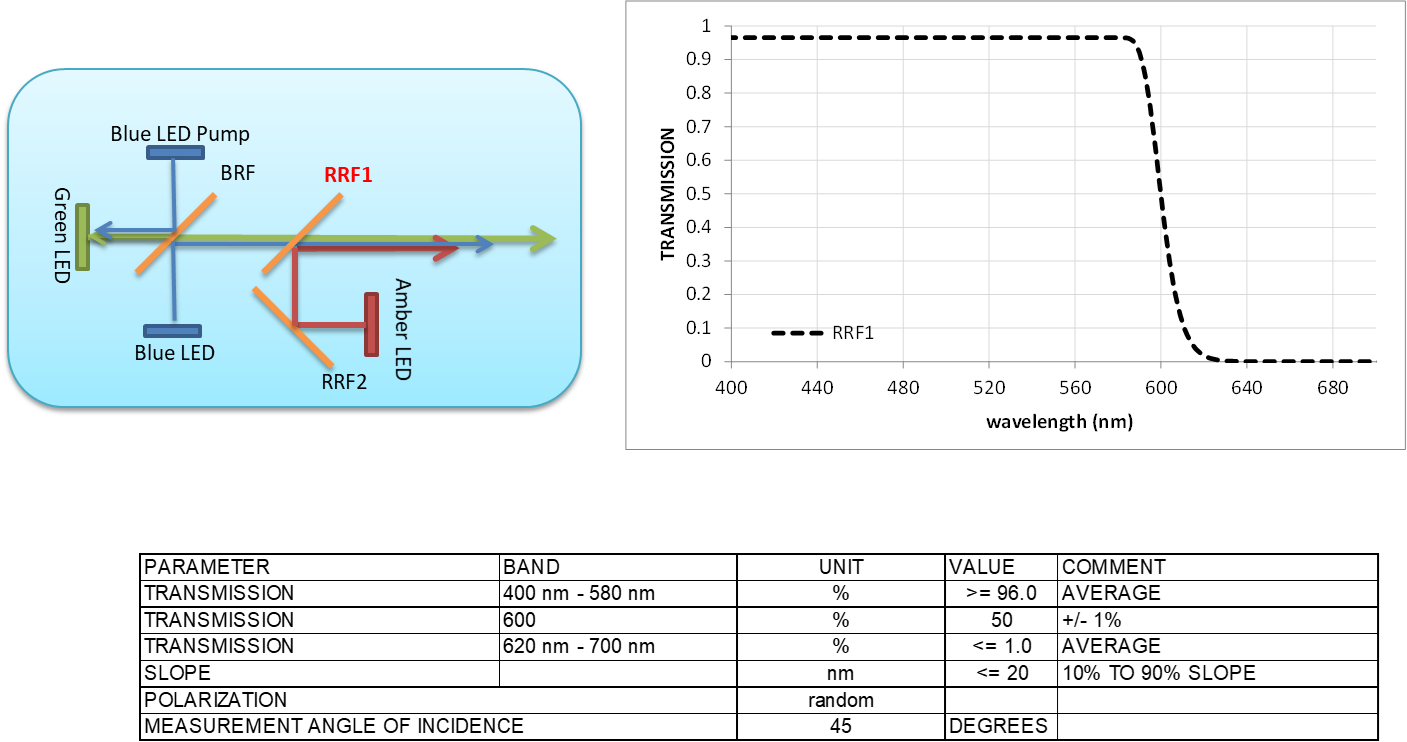 Figure 1-10 Blue-Green/Red Dichroic Filter Design
(Red Reflect Filter 1, RRF1)
Figure 1-10 Blue-Green/Red Dichroic Filter Design
(Red Reflect Filter 1, RRF1)If using a long wavelength red assist LED configuration, the filter curve varies depending on the wavelength of the long wavelength red LED or red Laser. Example dichroic filter curves are shown in the following figures, one for red LED / long wavelength red LED and one for red LED / red laser.
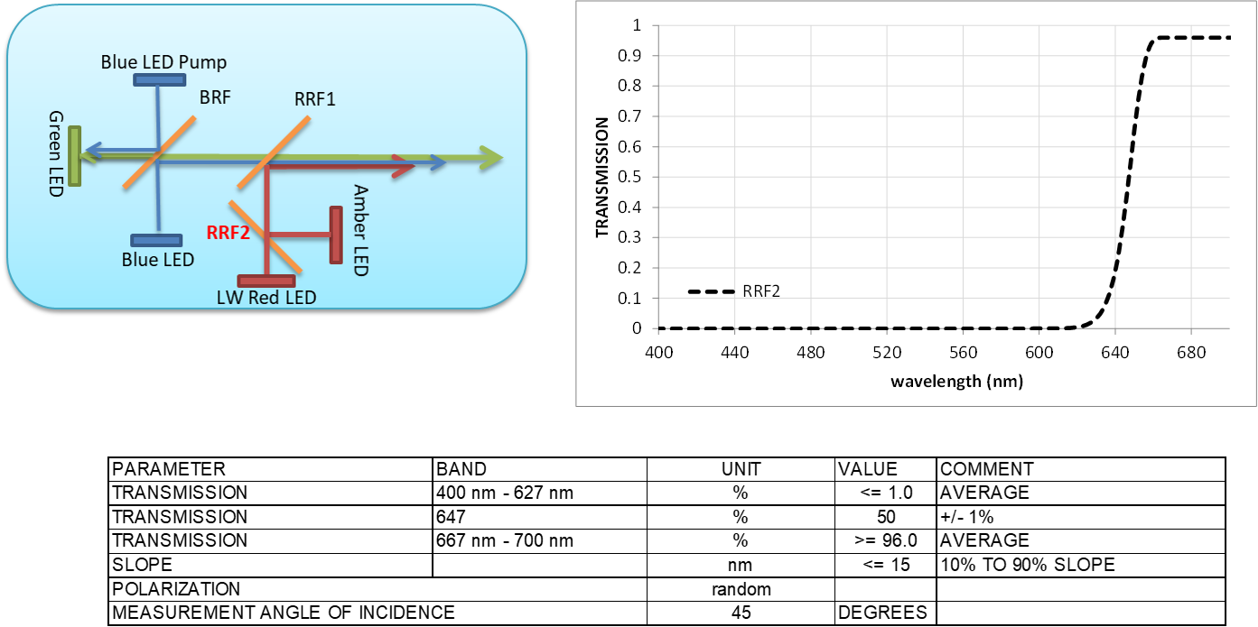 Figure 1-11 Long Wavelength Red LED Filter Design
(Red Reflect Filter 2, RRF2)
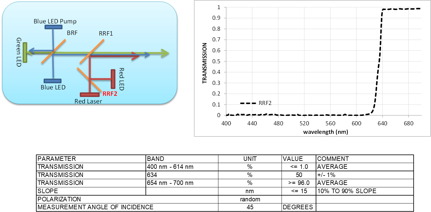 Figure 1-12 Red Laser Filter Design (Red Reflect
Filter 2, RRF2)
Figure 1-12 Red Laser Filter Design (Red Reflect
Filter 2, RRF2)For high quality saturated colors that reach the P3 color standard, in addition to long wavelength assist configuration, the green light can be filtered after the green/blue combination dichroic filter to create a more saturated green color. This wide color gamut comes at the expense of about 15% of the lumens of a long wavelength red assist projector, but allows projection of nearly the P3 chromaticity gamut. If this filter can be moved in and out of the beam, the projector can operate in a high brightness mode (with filter removed) or a cinema mode (with saturated colors). This dichroic color filter is placed normal the optical path, so the AOI is 0°.
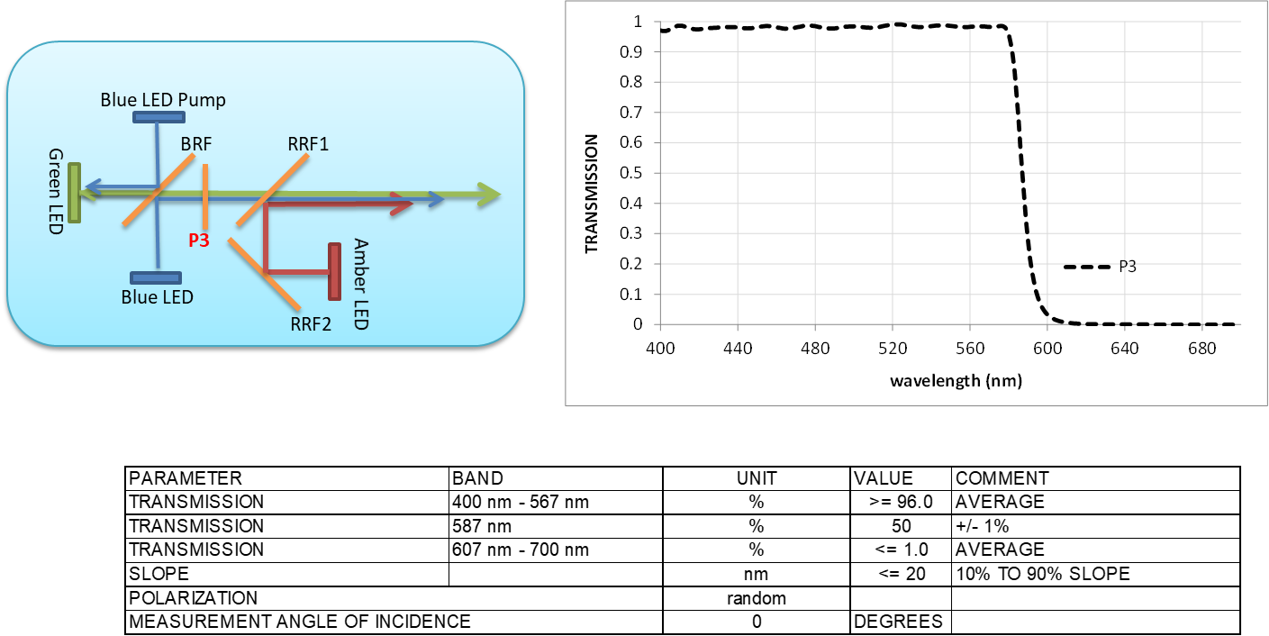 Figure 1-13 P3 Chromaticity Gamut LED Filter
Design
Figure 1-13 P3 Chromaticity Gamut LED Filter
DesignLayout of LED Illuminators With Examples
The combination of the collimator optical design, the choice of architecture (RGB, RGBB, RGBB+long wavelength red), the selection of the color filters and the illumination architecture all combine to a practical layout for the LED illuminator for projection systems. Figure 1-14 through Figure 1-16 show several examples of the most common LED optical layouts for projection systems.
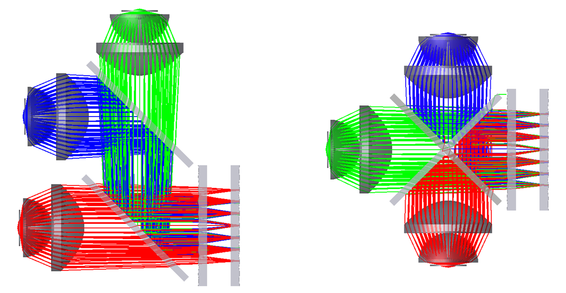 Figure 1-14 RGB Standard Layout and X-Plate
Layout
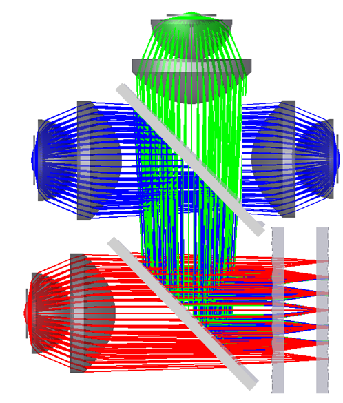 Figure 1-15 RGBB Layout Example
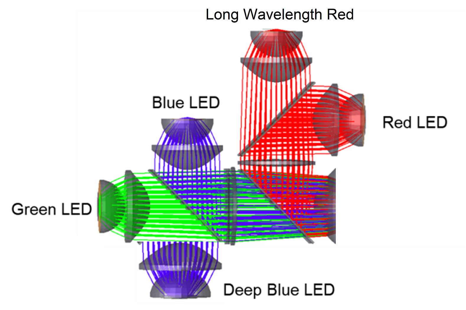 Figure 1-16 RGBB + Long Wavelength Red Layout
Example
Figure 1-16 RGBB + Long Wavelength Red Layout
ExampleSummary
The rapid development of LEDs as projector light sources has made single chip, high lumen LED projectors possible. LED illumination when paired with single chip DLP projection technology offers advantages in efficiency, reliability and image quality. These systems naturally produce vibrant and vivid color images with a wide color gamut. High power LEDs continue to improve in efficiency and brightness as LEDs become a dominant source of lighting for all applications.