SBOA174D december 2016 – april 2023 INA240 , INA240-Q1 , INA253 , INA253-Q1 , INA254 , INA280 , INA280-Q1 , INA281 , INA281-Q1 , INA290 , INA290-Q1 , INA293 , INA293-Q1
1 TI Tech Note
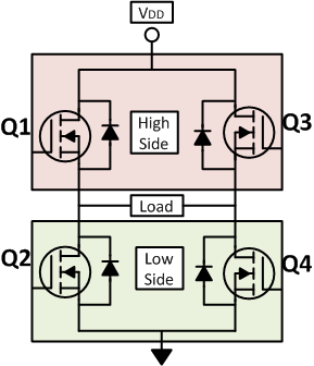
The semiconductor industry has always looked for improvements in creating technology that has the ability to enable higher power density systems. One such circuit is an H-bridge. As shown in Figure 1 an H-bridge is a simple circuit consisting of 4 FET transistors connected between the load. An H-bridge is often used when the direction of the current is required to be controlled and managed from the supply to the load. If the load is highly inductive, the energy stored in the load can also be discharged safely to ground by controlling the H-bridge. H-bridge circuits are commonly used in motor control, DC-DC converters, audio sub systems and LED lighting control making systems more safe and reliable. H-bridge consisting of silicon FET transistors often achieve > 95% efficiency, while GaN FET transistors can allow for efficiencies beyond 99%. A higher efficiency H-bridge combined with current sense amplifiers to monitor, manage, and control the load currents leading to improvement in safety, reliable, and overall improvements in the power efficiency of an end equipment.
 Figure 1 H-Bridge Circuit
Full H-Bridge Circuit Configuration and Control
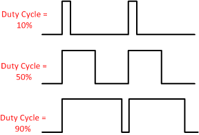
The H-bridge can be controlled by turning ON and OFF the FETs. A pulse-width modulation (PWM) scheme is an effective method used in creating different waveforms to control the flow of current. By controlling the duty cycle of the PWM waveform the current flowing to the load can be effectively controlled. Figure 2 depicts the PWM waveform with different duty-cycles. By modulating the duty cycle of the PWM generator, the output current to the load can be precisely controlled.
 Figure 2 Pulse Width Modulation Scheme
for H-Bridge
Figure 2 Pulse Width Modulation Scheme
for H-BridgeWhile controlling the H-bridge using PWM waveforms careful consideration must be taken into account to make sure there is no direct short from battery to ground. For example, in Figure 1, do not turn Q1 and Q2 on simultaneously. Such a scenario creates a high current shoot through which can damage the corresponding electronic drive circuitry. Table 1 describes the possible states of a full H-bridge control.
| Q1 | Q2 | Q3 | Q4 | State of Load |
|---|---|---|---|---|
| ON | OFF | OFF | ON | Current flows from H-bridge to the load |
| OFF | ON | ON | OFF | Direction of the current to the load is reversed |
| OFF | ON | OFF | ON | Provide safe path for the load to discharge to ground |
| ON | OFF | ON | OFF | Recirculation current stored in the load |
| OFF | ON | OFF | ON | Recirculation current stored in the load |
| ON | ON | OFF | OFF | Short circuit from battery to ground |
| OFF | OFF | ON | ON | Short circuit from battery to ground |
| ON | ON | ON | ON | Short circuit from battery to ground |
Current Measurement in an H-Bridge for Motor Control
Bidirectional current sensing in a full H-bridge motor control is critical for safety and reliability to monitor and control a system. An accurate current measurement in an H-bridge can control the torque of the motor precisely or precisely set the position in a stepper motor.
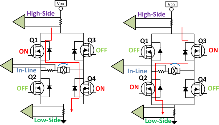
Figure 3 describes common locations to measure current in an H-bridge: high-side, in-line, and low-side. As motors are highly inductive, the PWM output tends to overshoot during low to high transitions and undershoot during high to low transition. The characteristics of overshoot and undershoot of an amplifier are important in selecting a correct component. A current sense amplifier that can sustain overshoot and undershoot conditions with a fast response time, and is able survive harsh requirements of an inductive system is critical. By providing valuable current sensing data to the system, this helps to detect anomalies in the motor or other inductive system features, which can lead to premature failures.
Table 2 describes the advantages and disadvantages of measuring currents in an H-bridge at multiple locations.
 Figure 3 Current Sensing Locations in
an H-Bridge Control
Figure 3 Current Sensing Locations in
an H-Bridge Control| Current Measurement | Pros | Cons |
|---|---|---|
| High-Side | Detect shorted load from battery for diagnostics | High voltage common-mode amplifier |
| In-Line | Direct motor current measurement, low-bandwidth amplifier | High dv/dt signals. PWM settling time |
| Low-Side | Low-cost, low common-mode voltage | Unable to detect shorted load |
The INA240 current sense amplifier can operate from a common-mode voltage ranging from –4 V to 80 V. In an H-bridge application, the INA240 can be used regardless of whether the measurement location is high-side, in-line, or low-side. A low offset of (25 µV) and low voltage offset drift (0.25 µV/°C) combined with a low gain error (0.2%) and gain drift (2.5 ppm/°C) makes it applicable for precise measurements regardless of system temperature. In addition to high performance DC specifications, the INA240 is also designed to operate and reject dv/dt transients enabling real time load current measurements at the in-line measurement location. The system level benefits of in-line sensing enables higher power density by lowering the processing power requirements for closed loop control system.
Alternate Device Recommendations
The INA241 is an ultra-precise analog current sense amplifier. The INA241 can be used in high-voltage bidirectional applications paired with 1-MHz bandwidth to offer fast response time with precise operation for in-line control within H-bridge applications. The INA241 can measure currents at common-mode voltages of –5 V to 110 V and survive voltages between –20 V to 120 V.
The INA253 or INA254 devices are ultra-precise current sense amplifiers with integrated low-inductive, precision 2-mΩ or 400-µΩ shunts with an accuracy of 0.1% or 0.5%, respectively, with a temperature drift of < 15 ppm/°C. The INA253 is limited to applications that need < ±15 A of continuous current at TA = 85°C, and the INA254 is limited to applications < ±50 A of continuous current at TA = 85°C. The INA253 and INA254 integrated shunt is internally Kelvin-connected to the INA240 amplifier. The INA253 and INA254 devices provide the performance benefits of the INA240 amplifier with the inclusion of a precision shunt providing a total uncalibrated system gain accuracy of < 0.2%.
The INA281 can be used in high-voltage applications such as high-side current sensing in a motor. The INA281 can measure currents at common-mode voltages of –4 V to 110 V and survive voltages between –20 V to 120 V, making this device versatile for a variety of applications where voltage can swing negative.
An option for low-side sensing is the INA381 which is a cost-optimized current sense amplifier with an integrated comparator which serves to reduce PCB footprint size and simplifies design.
| Device | Optimized Parameter | Performance Trade-Off |
|---|---|---|
| INA241 | Vcm range: –5- to 110-V bidirectional | IQ is slightly greater |
| INA281 | Vcm range: –4 V to 110 V | Unidirectional |
| INA381 | Integrated comparator | Vcm limited to 26 V |
| INA253 | Integrated shunt 2 mΩ, VCM range: –4 V to 80 V | ±15-A maximum continuous current |
| Integrated shunt 400 µΩ, VCM range: –4 V to 80 V | ±50-A maximum continuous current |
| Document | Title |
|---|---|
| SBOA160 | Low-Drift, Precision, In-Line Motor Current Measurements With PWM Rejection |
| SBOA176 | Switching Power Supply Current Measurements |
| SBOA163 | High-Side Current Overcurrent Protection Monitoring |
| SBOA187 | Current Mode Control in Switching Power Supplies |