SLLA554 april 2023 ISO1042 , ISO1042-Q1 , ISO1044 , ISO1050 , ISO7762-Q1 , TCAN1146-Q1
1 Application Brief
In the past, power train and body electronics sub-systems in internal combustion engine vehicles used only 12-V battery and hence non-isolated controller area network (CAN) devices were sufficient for in-vehicle networking. But with the advent of hybrid electric vehicles (HEV) and electric vehicles (EV), more and more non-isolated CAN nodes in these subsystems are going the isolated way.
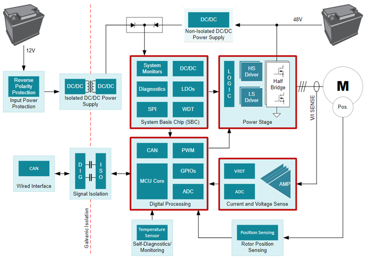
Depending on the electronic control unit (ECU), signal isolation requirements may vary. Non-isolated CAN may suffice for some while isolated CAN could be necessary for the others. An example of isolated CAN usage is the belt starter generator shown in Figure 1 for a HEV where the micro-controller on the high-voltage side needs to communicate with the 12-V side using CAN communication with isolator providing the protection of the LV side from the HV side.
 Figure 1 Belt Starter Generator
Sub-system
Figure 1 Belt Starter Generator
Sub-systemThe isolated CAN requirements also differ from system to system. Isolated CAN transceivers such as ISO1042-Q1 meet the requirements of systems that have isolated power supply on both sides of the isolator continuously present. This may be the case in systems like power train where the CAN transceiver needs to be continuously on to monitor safety critical functions and pass this information to the microcontroller. Since the microcontroller (MCU) and the isolated CAN transceiver are on continuously, this leads to increased power consumption.
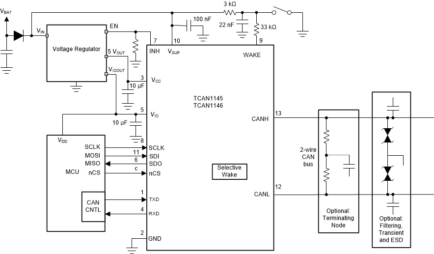
To reduce the overall power consumption in the car, it can be beneficial to turn off the CAN transceiver and the micro-controller not monitoring safety critical signals. Non-isolated CAN transceivers with wake up such as the TCAN1043-Q1 and TCAN1144-Q1 allow for all the CAN transceivers to wake up at the same time while CAN transceivers that support partial networking such as the TCAN1146-Q1, as shown in Figure 2, allow for a single CAN node to wake up thereby saving more power.
 Figure 2 TCAN1146-Q1 Simplified
Schematic
Figure 2 TCAN1146-Q1 Simplified
SchematicFigure 3 shows the implementation of the CAN transceiver with selective wake up in an isolated CAN system. To implement the functionality of CAN with wake up or partial networking in an isolated CAN subsystem would require the isolator to have enough channels for communication between the microcontroller and the CAN transceiver.
 Figure 3 Implementation of Discrete
 Isolated CAN Solution
It is evident from Figure 3 that four channels of isolation are needed for SCLK,SDI, nCS, and TXD signals from MCU to the CAN device while two channels are required for the SDO and RXD signal from CAN transceiver to the MCU. The digital isolator ISO7762-Q1 meets the requirements for the number of channels. Another concern with CAN systems is the timing specifications, namely tLOOP and tBIT which need to be compliant with the ISO 11898-2:2016 standard.
Table 1 shows these specifications for the TCAN1146-Q1 over the operating temperature range while Table 2 provides the timing specifications of the isolator ISO7762-Q1 over the same temperature range.
| ISO 11898-2:2016 | TCAN1146-Q1 | |||
|---|---|---|---|---|
| MIN | MAX | MIN | MAX | |
| t LOOP | 255 ns | 215 ns | ||
| tBIT(BUS) 2 Mbps CAN FD | 435 ns | 530 ns | 440 ns | 525 ns |
| tBIT(BUS) 5 Mbps CAN FD | 155 ns | 210 ns | 160 ns | 205 ns |
| tBIT(RXD) 2 Mbps CAN FD | 400 ns | 550 ns | 410 ns | 540 ns |
| tBIT(RXD) 5 Mbps CAN FD | 120 ns | 220 ns | 130 ns | 210 ns |
| ISO7762-Q1 | |||
|---|---|---|---|
| MIN | MAX | ||
| tPLH, tPHL | Propagation delay time | 6ns | 16 ns |
| PWD | Pulse width
distortion |tPHL – tPLH| |
4.9 ns | |
The resulting timing specifications of the discrete isolator and CAN transceiver are shown in Table 3. It is evident that the discrete solution of ISO7762-Q1 and TCAN1146-Q1 meets the ISO 11898-2:2016 standard up to CAN Flexible Data Rate (FD) speed for 5 Mbps.
Another point to consider while adding the isolator to the systems is the need for the isolated power supply to power the secondary side of the isolator and the microcontroller. A simplified schematic is shown in Figure 4, where the transformer driver SN6505A-Q1 along with an external transformer provides the secondary voltage Viso that is used to power up the secondary side of the isolator as well as the MCU.
The High voltage supply pin of the CAN transceiver (VSUP) is supplied by the battery voltage of 12V that is always present. The power supply of the transformer driver and the 5-V CAN supply voltage (Vcc) are obtained from the LDO that steps the voltage from the battery voltage to 5 V. The enable pin of the LDO is controlled by the inhibit pin (INH) of the CAN transceiver. In sleep mode, the INH pin is off, going into a high-Z state, thereby disabling the LDO. This allows the node to be placed into the lowest power state with the Isolator, isolated power supply and MCU off. When the INH pin switches high in the wake up mode, the LDO gets enabled and it turns on the isolator, the isolated power supply and MCU, thereby preparing the system to be ready for whatever mode (Normal, Standby, or Listen) the CAN transceiver decided to enter.
 Figure 4 Isolated CAN with Wake Up
System
Figure 4 Isolated CAN with Wake Up
SystemIn conclusion, discrete implementation of digital isolator along with a suitable CAN transceiver with selective wake features can ensure the low power needs of such systems coupled with the safety feature of isolated systems. Isolation does add complexity to the system design when it comes to the system timing performance and isolated power supply considerations. The ISO7762-Q1 and TCAN1146-Q1 along with an isolated power supply meet the timing and power requirements of isolated CAN FD systems up to 5 Mbps.
| ISO 11898-2:2016 | ISO7762-Q1 + TCAN1146-Q1 | |||
|---|---|---|---|---|
| MIN | MAX | MIN | MAX | |
| tLOOP | 255 ns | 247 ns | ||
| tBIT(BUS)2 Mbps CAN FD | 435 ns | 530 ns | 435.1 ns | 529.9 ns |
| tBIT(BUS)5 Mbps CAN FD | 155 ns | 210 ns | 160 ns | 205 ns |
| tBIT(RXD) 2 Mbps CAN FD | 400 ns | 550 ns | 400.2 ns | 549.8 ns |
| tBIT(RXD) 5 Mbps CAN FD | 120 ns | 220 ns | 130 ns | 210 ns |